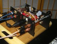
I like the way you set up the "box" for the amp (as per the photo a few posts ago). Two pieces of acrylic plates should work well. I am going to give this a try (I was never good at building chasis).
Let us known how the Bourn 22 uH coils work.
Regards,
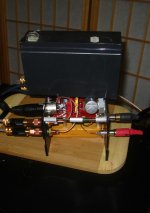
Thanks, Will do. I used some plastic dividers that came with some parts bins. It makes it easier to get to things when you're "fiddling" with it and I place an SLA battery on it to stop the "tug-o-war" from the cables.
Attachments
Radiosmuck,
Are you wanting to turn your 2.1 board into a 2x100 watt board? It might be tricky but could be done by bypassing one of the coils (follow Fig 27 of the TI tech sheet http://www.ti.com/lit/ds/symlink/tpa3118d2.pdf ), and convert the top circuit into the bottom circuit - basically connect pin 27 to the input of the upper inductor, and pin 23 to the input of the lower inductor, then connect the left channel inputs pins 10 & 11 to ground, the right channel input stays as is. Then the negative of the left channel is the bridge tied negative and the positive of the right channel is the positive of the bridge tied positive. You will now have 2 banks of unused coil filter chokes and EMI/RF filter network after the coils.
Are you wanting to turn your 2.1 board into a 2x100 watt board? It might be tricky but could be done by bypassing one of the coils (follow Fig 27 of the TI tech sheet http://www.ti.com/lit/ds/symlink/tpa3118d2.pdf ), and convert the top circuit into the bottom circuit - basically connect pin 27 to the input of the upper inductor, and pin 23 to the input of the lower inductor, then connect the left channel inputs pins 10 & 11 to ground, the right channel input stays as is. Then the negative of the left channel is the bridge tied negative and the positive of the right channel is the positive of the bridge tied positive. You will now have 2 banks of unused coil filter chokes and EMI/RF filter network after the coils.
Just received my 2x50W amplifier : TPA3116 Amplifier Board( 50W+50W ) D Class Amplifier Board-in Amplifier from Consumer Electronics on Aliexpress.com
Right now it is powered with their PSU : Aliexpress.com : Buy MUSE 12V 4A power supply for muse T AMP M20 M21 from Reliable MUSE 12V 4A power supply suppliers on ThanksBuyer
And it works like a charm.
Quite impressive, the sound is really nice, and it really has a lot of power, even with 12V only !
Right now it is powered with their PSU : Aliexpress.com : Buy MUSE 12V 4A power supply for muse T AMP M20 M21 from Reliable MUSE 12V 4A power supply suppliers on ThanksBuyer
And it works like a charm.
Quite impressive, the sound is really nice, and it really has a lot of power, even with 12V only !
Even with 4A only! Can't wait for this.
But as far as I can remember from the spec-sheet, this chip actually can run off 4V, or do I remember wrongly?
But as far as I can remember from the spec-sheet, this chip actually can run off 4V, or do I remember wrongly?
Last edited:
it doesn't work that way. the distortion follows the power supplied to the module. if you supply 19v and expect to draw a clean 40w from it you'll be mistakenly wrong.Before buying that specialty power supply, connect any old laptop 19 volt brick you have lying around. We all have at least 3 of them from old pc's. It may plug right into the jack on that board. Listen to it and I think you will see that it provides you all the watts you will need for 95% of the time. The 3116 is a 50 watt nominal rated chip with 10% distortion at 50 watts so you really don't want to operate there anyway. If you stay below 40 watts I think the distortion figure is about 0.1%. The basic equation for volts as a function of power and impedance is P=V^2/R, solve for V=sqrt(P R). For 40 watts and 8 ohms, V=sqrt(40 x 8)=sqrt(320)=17.9volts. Thus a 19 volt 90 watt power supply is perfect for driving this amp at up to 40 watts, which you really don't want to go above anyway.
So, the power supply you need, you probably have already, if not order a no-name brand one or a HP (with grounded plug) for $8 on Amazon or the like.
at 19v supply you'll only get ~26W at 10% THD and only about ~21W at 1% THD into 8 ohm.
i've placed order for mine and waiting for it to arrive.
minimum supply voltage is 4.5vEven with 4A only! Can't wait for this.
But as far as I can remember from the spec-sheet, this chip actually can run off 4V, or do I remember wrongly?
Do you have suggestion for a suitable PSU?it doesn't work that way. the distortion follows the power supplied to the module. if you supply 19v and expect to draw a clean 40w from it you'll be mistakenly wrong.
at 19v supply you'll only get ~26W at 10% THD and only about ~21W at 1% THD into 8 ohm.
i've placed order for mine and waiting for it to arrive.
previous audition carried out locally shows that the venerable tripath ta2024/ta2020 performs best with a good quality smps (compared to linear or even regulated power supply).Do you have suggestion for a suitable PSU?
out of a few smps tested, high current smps from meanwell is the best. but that's for tripath chips, no idea how this module would perform. but they share some major similarities so if i were to buy one, i'd get the meanwell.
the tpa3116 have an absolute max supply at 30V, recommended max supply at 26V. so a meanwell 24V should do well here since it has a pot to tune output voltage. i'd buy a 4A minimum, though something around 10A would always be better, and tune the output voltage to 26V. that should provide ~38W clean into 8 ohm (70W into 4 ohm).
Even with 4A only! Can't wait for this.
But as far as I can remember from the spec-sheet, this chip actually can run off 4V, or do I remember wrongly?
I must add that I have only played through Pro Tools with a lot of Eqying and dynamics control (because of my DIY speaker). Especially a low cut at 70Hz with a high slope.
But still the sound is great, even compared to my old Sansui amplifier or to my amp6.
Just out of interest I have just connected a 6v 1200ma wall wart to my 3116 board and it works just fine.minimum supply voltage is 4.5v
I have noticed no difference between 24V - 12V - 6V, but I do have very efficient speakers.
if properly designed, there shouldn't be any degradation of sound quality between the minimum and maximum voltage supplied or somewhere in between, unless you're drawing near clipping. from the looks of it, you're not anywhere close to clipping.Just out of interest I have just connected a 6v 1200ma wall wart to my 3116 board and it works just fine.
I have noticed no difference between 24V - 12V - 6V, but I do have very efficient speakers.
at 6v you're seriously power limited, but the output to each speaker is bridged mode, and if the speakers is 4 to 6 ohm then you should have at least a couple watts of clean power.
Actually, my speakers are vintage 15 inch x 15 OHM, in very large corner enclosures and at a serious listening level I'm only drawing 0.085 watts/chif properly designed, there shouldn't be any degradation of sound quality between the minimum and maximum voltage supplied or somewhere in between, unless you're drawing near clipping. from the looks of it, you're not anywhere close to clipping.
at 6v you're seriously power limited, but the output to each speaker is bridged mode, and if the speakers is 4 to 6 ohm then you should have at least a couple watts of clean power.
Last edited:
it doesn't work that way. the distortion follows the power supplied to the module. if you supply 19v and expect to draw a clean 40w from it you'll be mistakenly wrong.
at 19v supply you'll only get ~26W at 10% THD and only about ~21W at 1% THD into 8 ohm.
i've placed order for mine and waiting for it to arrive.
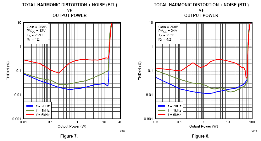
Not sure what spec you are looking at that says what you claim. If you look at TI spec sheet Fig. 7 and Fig. 8 they show THD curves for 12V and 24V power supply, respectively. For the 12V case, the steep transition to high distortion occurs at circa 15 watts (into 4 ohms), and for the 24V case, the transition to high distortion occurs at about 50 watts. Below these transition "walls", the distortion is circa 0.1%. If I linearly interpolate where that high distortion wall is located for a 19V power supply, I get about 43 watts. Do you have data or graphs from TI that show otherwise?
See graphs pulled from their spec sheet below.
Attachments
Last edited:
why assume when it's already measured?Not sure what spec you are looking at that says what you claim. If you look at TI spec sheet Fig. 7 and Fig. 8 they show THD curves for 12V and 24V power supply, respectively. For the 12V case, the steep transition to high distortion occurs at circa 15 watts (into 4 ohms), and for the 24V case, the transition to high distortion occurs at about 50 watts. Below these transition "walls", the distortion is circa 0.1%. If I linearly interpolate where that high distortion wall is located for a 19V power supply, I get about 43 watts. Do you have data or graphs from TI that show otherwise?
See graphs pulled from their spec sheet below.
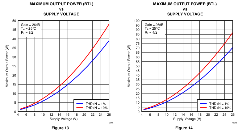
it's 2 page down from your figure.
from my experience with the ta2024, a couple of watt is fine with music. but they start to run out of breath with movies, rock music or music with lots of bass program.Actually, my speakers are vintage 15 inch x 15 OHM, in very large corner enclosures and at a serious listening level I'm only drawing 0.085 watts/ch
Missed that graph, well it does show about 40 watts at 19 volts for 1% THD for 4 ohms which is what my speakers are.
I don't remember if I mentioned it before (or if someone else did) but if not, just a reminder that this board swaps it's stereo channels.
I don't remember if I mentioned it before (or if someone else did) but if not, just a reminder that this board swaps it's stereo channels.
Did not know that - good to know. I discovered the same thing about the 3.5 mm input jack on the Lepai 2020+ (RCA inputs is fine). Seems like such a basic thing that it amazes me people go to production with a big blunder like this.
I don't remember if I mentioned it before (or if someone else did) but if not, just a reminder that this board swaps it's stereo channels.
Not that I can remembered. Do you mean the Left-in becomes the Right-out?
Hey, just received my amp today 😀. The amp was quite well-packaged. The soldering seems clean and tidy. Did not realised that the volume control is so small. Plan to work on it this weekend.
Regards,
Not that I can remembered. Do you mean the Left-in becomes the Right-out?
Hey, just received my amp today 😀. The amp was quite well-packaged. The soldering seems clean and tidy. Did not realised that the volume control is so small. Plan to work on it this weekend.
Regards,
Yes, just swap the L & R at the input and you'll be good.
You owe it to yourself to change the volume control to something a bit better. I've tried six or seven different ones and although all were different, they were all an improvement over the stock one. I've put the 10K Alps K-Fader back in this one and am really loving the way this amp sounds.
Have fun!
Attachments
- Home
- Amplifiers
- Class D
- TPA3116D2 Amp