Thanks! You’d think, but they’re doing well. Hottest part on the heatsink is 45c; top of Tokin package is 50c, and hottest spot on chokes is 50c. Helps that these are beefy sinks 🙂


Without changing anything else on my setup I attached some computer fans I had lying around:

This helped. I was measuring ~150deg F on each SIT after 15min. Still, I knew the thermal pads were way too thick so I ended up removing the SITs and sinks and redoing the whole interface.
Back to passive cooling: after 15 min the temperatures are far lower:

Dropping the pads from 3mm to 0.5mm helped. Not sure what I was thinking when I reached for the thick ones 🤦♂️
I can also measure the sinks getting hotter within 10deg or less of the SITS, which wasn’t happening with the thick pads. I can also hold my finger on the top of the SITs indefinitely, proving my laser thermometer isn’t too far off.
The end game is still to have active cooling, but with a low profile shroud and fan ducting that will occupy the open hole in the front plate below the sinks.
This helped. I was measuring ~150deg F on each SIT after 15min. Still, I knew the thermal pads were way too thick so I ended up removing the SITs and sinks and redoing the whole interface.
Back to passive cooling: after 15 min the temperatures are far lower:
Dropping the pads from 3mm to 0.5mm helped. Not sure what I was thinking when I reached for the thick ones 🤦♂️
I can also measure the sinks getting hotter within 10deg or less of the SITS, which wasn’t happening with the thick pads. I can also hold my finger on the top of the SITs indefinitely, proving my laser thermometer isn’t too far off.
The end game is still to have active cooling, but with a low profile shroud and fan ducting that will occupy the open hole in the front plate below the sinks.
Attachments
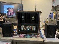
It would certainly make a good match for my Teac 4010!
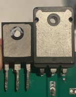
Bias is ~1.4A nominally. The SITs were decently matched. 35~40W dissipation each.
I've been able to listen on and off as I've tested, just never for too long due to the heat transfer issues. Now that I'm on the right track I will hook it up to my nicer speakers and get some extended listening in!
Bias is ~1.4A nominally. The SITs were decently matched. 35~40W dissipation each.
I've been able to listen on and off as I've tested, just never for too long due to the heat transfer issues. Now that I'm on the right track I will hook it up to my nicer speakers and get some extended listening in!
look like the heatsink are on wood ? no pad need ,or teflon spacer ...and better air flowWithout changing anything else on my setup I attached some computer fans I had lying around:
View attachment 1134852
This helped. I was measuring ~150deg F on each SIT after 15min. Still, I knew the thermal pads were way too thick so I ended up removing the SITs and sinks and redoing the whole interface.
Back to passive cooling: after 15 min the temperatures are far lower:
View attachment 1134854
Dropping the pads from 3mm to 0.5mm helped. Not sure what I was thinking when I reached for the thick ones 🤦♂️
I can also measure the sinks getting hotter within 10deg or less of the SITS, which wasn’t happening with the thick pads. I can also hold my finger on the top of the SITs indefinitely, proving my laser thermometer isn’t too far off.
The end game is still to have active cooling, but with a low profile shroud and fan ducting that will occupy the open hole in the front plate below the sinks.
Last edited:
The heat sinks are mounted to an anodized plate and connected to the internal metal chassis. I need the pads or else the chassis will become live and create a direct short with ground.
I did an extended listening session with the new setup and the temp on both SITs stays below 100deg F. Happy with that and time to push forward with finishing the build.
I did an extended listening session with the new setup and the temp on both SITs stays below 100deg F. Happy with that and time to push forward with finishing the build.
That nice because your 109,8F pics after the 0,5 pad mod do not look well for summer time
btw the teflon spacer in my post was just in case of Alu plate to avoid short as you note
Ciao
btw the teflon spacer in my post was just in case of Alu plate to avoid short as you note
Ciao
Has anyone yet tried "reversing" the polarity of the TDV power supply - basically moving the choke, if one is using one, to the negative side of what follows the bridge rectifier? Isn't that the gist of it? If one is not using a choke isn't that already in effect?
Am I missing something?
Am I missing something?
Hi Rick, it is more than that because you have to change your grounding scheme as well. The choke would stay where it is, we are just flipping the supply. I can draw a schematic, if you are interested.
Since I am getting ready to make the change to my Bushes I would be immensely grateful, ra7.
I have copied Ben Mah's power supply schematic to make it easy for other's to reference.
So do we change where the input load resistor is terminated?
Would this disallow your trick for adding bias - not that i think this will be needed - I hope it isnt in my case.

Thanks,
I have copied Ben Mah's power supply schematic to make it easy for other's to reference.
So do we change where the input load resistor is terminated?
Would this disallow your trick for adding bias - not that i think this will be needed - I hope it isnt in my case.
Thanks,
Here's the schematic, Rick.

Notes:
1. Cannot skip C1 anymore.
2. Note that at the signal input, the signal common (or ground) must be connected to PS ground, or the VFET drain, not the bottom of R4.
3. Same for the speaker output. One terminal comes from VFET source (labeled speaker_minus), other from VFET drain (labeled speaker_plus), or ground in this case.
Compare and contrast this with the schematic in post 26, which uses a positive supply.
Ben's supply schematic above should work fine.
If using the 193V (1.0 ohm DCR) and trying to achieve higher bias but not getting there with R1 = 0, connect R4 leg to the point between R1 and the 193V and size R1 for desired bias.
BTW, I have built the one with the positive supply and it is dead quiet on my 110 db/W horns. Not saying there is no improvement to be had, but be careful in this operation. I know I would triple check everything and power it up slowly with a Variac, one channel at a time.
Last edited:
I am curious why speaker positive is connected to Ground (both V+ and V- versions)?
The single ended SIT follower does not invert phase, but it has positive phase H2. Was it done for negative phase H2?
The single ended SIT follower does not invert phase, but it has positive phase H2. Was it done for negative phase H2?
- Home
- Amplifiers
- Pass Labs
- Total Domination VFET (TDV) Amp (using 2SK2087C)