It seems to be consensus that the transformer cannot tolerate high supply voltage.
The presence of some DC may make this worse.
you can use a Mains Bulb Tester between the Variac and your transformer.
This will limit start up current very effectively and ensure you don't overload your small Variac.
my Variac is 2.75A 240Vac so cannot supply big currents. I have never damaged it even into 1kVA transformers.
Have you read my posts on plotting the curve Ipri vs Vprimary.
You will learn something about your transformer if you do this. Either it has adequate primary turns for your supply voltage range, or that it has not.
Big toroidal tranformer => Very low impedance + DC => Saturation => Hum, buzz, heat
I think you have a blown transformer.
I think you have a blown transformer.
Last edited:
Enhanced and clarified images to see details:


Aleksandar (al_tsankov)
Now I'm waiting for 55mm thread spacers needed for supporting the upper two PCBs (they are custom made due to their length) and it will be ready for shipment...
...Can I very slowly turn up the variac..
The Toroid buzz was particularly bad...
Hi Peter
Your thread has raised some educational questions.😉
Rather than slowly turn up the Variac, why not start the amp as normal with the Variac turned up and then just turn it down?
If the noise drops then the transformer is a bit too close to saturation.
Seems quite possible for a sound reinforcement amplifier where transformer mechanical hum/buzz was probably not a priority.
This is also consistent with your comments that the DC blocker doesn't seem to help and that the amp has done this from the start.
Second point, you say the buzz was particularly bad - can you simply measure the line Volts and see if the worse noise correlates with positive fluctuations?
That seems quite possible too, you say you are on a rural grid, sometimes these are not very closely stabilized.
Best wishes
David
Last edited:
My Adcom 7000 picked an oscillating hum from the transformer when I bought a plasma tv and plugged it in, unplugged it, no hum. Drove me nuts until I bought a humbuster from AVA HiFi.
Plasma TV and air conditioner generate DC.
I have both but I have more DC with them off. They were off when I measured 2.7 Vdc and 2.1 Vdc.
I have both but I have more DC with them off. They were off when I measured 2.7 Vdc and 2.1 Vdc.
Thanks again, everyone;
Mr. David Zan, regarding starting the amp with variac at full, I have my variac installed with a 1 amp ac amp meter, and thought it easier just to start at minimum, so as not to burn out the variac or meter.
The Crest amp has a soft start but I am guessing that even that will exceed the 1 amp meter.
BTW; I think this significant; The Toroid is quiet during the soft start. I checked the schematic, and the soft start resistors are in the primary.
I don't know if the toroid is quiet during 'soft start' because it is loaded by cap charging or because of the reduced line voltage. The variac test will resolve this.
Could I harm the amp by starting it very slowly with the variac? (Probably a dumb question, but since I have the ear of the experts, better safe than sorry).
I only ask this because I almost burned out a VU meter on a Phase Linear 700B, starting with my variac, because the turn on 'thump' turned into a prolonged DC output swing until the amp powered up, The Crest, although more powerful, hopefully is a little more civilized.
Maybe. It depends on the design. But soft starts and similar may not drop out. This would burn out primary line resistors................ Could I harm the amp by starting it very slowly with the variac?.................
Test the transformer alone with open secondaries and no softstart.
Use the Bulb Tester as your current limiter.
A 40W 115Vac light bulb will have a hot resistance of ~330r
The cold resistance will be ~10% ot his i.e. 33r
33r in the 115Vac circuit will limit the current to 3.5Aac but that will drop very rapidly as the transformer flux builds and the filament heats.
If you have a very small transformer you could go down to a 25W Bulb.
If you start with the Variac turned down to zero, the starting current will be zero.
To avoid problems of the soft start not dropping out and extended thumps from the amp causing damage internally, just turn on the amp with the variac on full, let everything settle down then wind it down and see if the humming stops. You can keep tweaking up and down to bring the hum in and out. If that works every time it is most likely a saturated core problem and you will have to find some way of reducing the voltage to the amp.
Even a pitiful 1A variac will be fine running an amp with no speakers connected. Class A amps excepted maybe.
Even a pitiful 1A variac will be fine running an amp with no speakers connected. Class A amps excepted maybe.
Input Voltage Setting
In looking at the datasheet for this amp I noticed that it can be factory configured to operate from 100 to 240VAC and claims to have "Crest's legendary overbuilt power supply". A saturated toroid core would hardly fall in to that category.
That said; is there a chance that the input voltage was set improperly; like at 100VAC? See attached datasheet for the note on sheet 2.
Attachments
Hi soundchaser001;
This makes perfect sense, if the amp was set for 100 volts instead of 120. I have downloaded a schematic for the CA-18 but I can't find the Toroid (or related primary taps on the drawing.
Here's the schematic, am I missing something?
I will look at the power supply pcb again, and try the variac, asap
Attachments
Yeah those are the pages I saw on line. No transformer wiring; just the PCB wiring. I suppose one way to tell is to check the internal rails (+/-120VDC yikes!) to see if they are significantly higher (say 145 VDC). That could indicate that the transformer is putting out too high a voltage. This could be a red herring as operating conditions are not specified for the schematic voltages (RHS of sheet 6). One would guess quiescent no signal though.
Good luck
Good luck
IIRC, 140V is normal. Output is 99 volts RMS at light load, and 85V in 4 ohms (which requires >120VDC). If it's more than 150V, then worry.
... the amp with variac at full, I have my variac installed with a 1 amp ac amp meter...
Hi Peter
The Variac itself should be fine to start at full load.
I would expect the amp meter to have some overload protection, so you should be OK... probably😉.
Is it a simple coil meter across a shunt? with protection diodes?
Or can you bypass it just for the turn on transient?
Worse case, would it be cheap/easy to replace if you lucked out?
I measured turn on transients on my own toroidal transformer with a shunt resistor and oscilloscope.
Made several successful tests, then had one where the phase of the power turn on just happened to combine with the remnant flux from the previous power off and saturated the core.
Took out the shunt resistor in a flash of spark and smoke😉
But not too bad, I was cautious with protection and it was just a cheap resistor.
That was a small but calculated risk, because I knew a Hall effect current sensor was safer but didn't have one handy.
So do be careful.
Best wishes
David
Last edited:
Hi everyone and thanks again.
I started the amp with the variac. The (1 amp FSD) meter was pegged as I ramped up the voltage. BTW, the 'fact' sheet mentioned that the amp draws 3 amps idling.
The amp is quiet at 110 volts, tolerable at 115, and quite noisy at 120. My line voltage is 123.6 this morning.
Regardless of what the spec sheet says ( 100 to 240 VAC), the sticker on the amp says 120 VAC. With careful inspection of the transformer, I have accounted for all the leads, and I can see only 2 wires for the primary, so I don't think it has been set up on a 100 Volt tap.
I may still attempt to measure the B + Voltages, but my feeling is that operating the amp at a line voltage which does not produce buzz, will compromise performance.
PS; I have seen the clip light flash several times with some Steely Dan. I am addicted to bass, and the system has not been properly EQ'd for some time, but this is a topic for another thread.
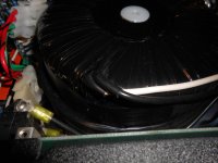
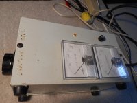
Here is yet another close up of the big offender. Shown also is my 'Variac in a box'. I need to install a bypass switch for the amp meter, and check the VA rating of the variac, but this started out as toroid noise issue.
Attachments
ATL Hi-Fi DC & Ripple Blocker x4 ME
ATL Hi-Fi DC & Ripple Blocker x4 ME (aka “Maty Edition”)
Remember: enhanced and clarified images to see details
ATL Hi-Fi DC & Ripple Blocker x4 ME (aka “Maty Edition”)
Remember: enhanced and clarified images to see details
An externally hosted image should be here but it was not working when we last tested it.
An externally hosted image should be here but it was not working when we last tested it.
An externally hosted image should be here but it was not working when we last tested it.
An externally hosted image should be here but it was not working when we last tested it.
An externally hosted image should be here but it was not working when we last tested it.
Maty,
what are the "pins" featured sticking out of the four receptacles?
Are they plastic "polarity" guides?
what are the "pins" featured sticking out of the four receptacles?
Are they plastic "polarity" guides?
Last night, Aleksandar (al-tsankov) answered me about the differences from DCBx2.
Look carefully at the bottom PCB - N wire (black) from IEC inlet goes directly to the N input terminal of that PCB. Then it goes directly to the output N terminal (doubled on that PCB) from which it goes to the 4 outlets - 2 wires from each terminal.
The difference between DCBx2 and DCBx4 is only on Ground wires - on DCBx2 I decided to route the ground via first PCB too, while on DCBx4 all 4 ground wires are connected on the star ground on the chassis ground point.
L wire from IEC goes to the L input of the first PCB, then from L output to the L input of the second (above the frist) then from L output of the second to the L input of the third (upper) and from it's output to the L input of the fourth (below).
Last edited:
The rear right PCB is the final (fourth) - the output connector is 5-terminal type L and N are doubled in order to have ability to attach 4 wires for L and N - two wires in one terminal. Well, it was a hard task but I managed to do that 🙂.
And yes - it can be said that output L and N wires are connected in a star points.
After a little joke he said:
....I have a PSU with 500VA toroidal transformer and every DCB I'm selling is tested with it prior to shipping
Last edited:
- Status
- Not open for further replies.
- Home
- Amplifiers
- Solid State
- Toroidal Transformer Noise