how do i get 9-12v ac from this transformerOutput Power: 132W
Insulating strength: 10Mohm, AC2000V/1min
Input Voltage (AC): 115V /230V 50Hz/60Hz
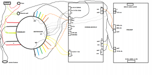
Output Voltage (AC): 0-200-220-260-280-320 (100mA) x2
0-6.3V (2A) x2
0-5V (5A)
0-18V (1A)
Insulating strength: 10Mohm, AC2000V/1min
Input Voltage (AC): 115V /230V 50Hz/60Hz
Output Voltage (AC): 0-200-220-260-280-320 (100mA) x2
0-6.3V (2A) x2
0-5V (5A)
0-18V (1A)
6+5=11V
Except that you need to keep the current to the lesser of the two windings that are in series.
You could parallel the two 6V windings for 4A. All the windings will need to be conected in the right relative polarities.
Last edited:
What do you need those 9-12VAC for?
Supposing it's for a tube amp or preamp, will the 5 or 6.3VAC be used for filaments?
Will you use the 18VAC winding?
Really, for a useful answer , you must supply as many details as possible,end use, a schematic if possible..
Otherwise it's like asking: "can I boil water with a BIC lighter?"
Supposing it's for a tube amp or preamp, will the 5 or 6.3VAC be used for filaments?
Will you use the 18VAC winding?
Really, for a useful answer , you must supply as many details as possible,end use, a schematic if possible..
Otherwise it's like asking: "can I boil water with a BIC lighter?"
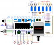
I am installing a MV04 2 Channel ALPS IR Remote Control Volume & Input Selection Module on a preamp IR remote control
ALPS Motorized volume control for 2 channels, board size: 120mm x 55mm
Input selection (4-to-1 way, stereo), board size: 130mm x50mm
input impedance: 100K Ohms
Supply voltage: 9-12V AC
ALPS Motorized volume control for 2 channels, board size: 120mm x 55mm
Input selection (4-to-1 way, stereo), board size: 130mm x50mm
input impedance: 100K Ohms
Supply voltage: 9-12V AC
how do you check polarity
Use the mfr's spec sheet if you have it. Otherwise, find out by trial and error.
One way in series they will add in voltage, the other way they'll subtract.
You won't need to parallel the 6V windings, since 2A is plenty.
Big overkill on the power rating of the transformer. Why not use a 9 or 12VAC wall wart?
Last edited:
The two 6.3 taps are being used already one for the tube power supply board and the other for the preamp board , i was going to splice into them for the mvo4
The two 6.3 taps are being used already one for the tube power supply board and the other for the preamp board ,
i was going to splice into them for the mvo4
Then I'd use a separate, cheap 9VAC wall wart. You can't do what you wanted, with the windings being used like that.
i can,t tie into the two 6.3 taps
No, because they're each being used for two different circuits. They can't be connected together.
You may be able to use ONE of the 6V windings (not the one for the 6X4 rectifier) with a voltage doubler
rectifier to get around 16VDC, and then use a regulator to reduce it to 9-12VDC. But this entire motor/drive
circuit will have to float and cannot be connected to ground anywhere, because of the other circuit that also
uses the same winding.
To be sure that you can do this, post the schematics of the boards that you are using.
Last edited:
Sounds like a pain I think I will take your suggestion and use a wall wart and just have two cords coming out the back thanks for the help.
I got a 9vac wall wart and hooked it up, everything works fine but I am getting an annoying hum still. Before i thought it was because I hooked it up to one of the power supply 12vdc tap
I am getting an annoying hum still.
The hum could be a ground loop, or a bad connection. How loud is it compared to the music?
Is it a low pitched hum, or a buzzing? Does it vary with the volume?
its the same all the time whether the volume is low or turned up ,you don,t here as much when the volume is up ,it wasn,t there before i installed the mv04
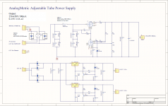
here is the schematics of the power supply and the preamp
Probably the hum is due to the way the various ground leads are connected.
Some of the grounds may have to be moved to a different connection point.
Can you post a photo of what you have now?
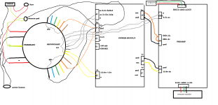
this how my grounds are know
The wiring looks ok. The preamp and the volume control boards both have the grounds of L+R channels connected together.
That can cause hum.
Last edited:
- Status
- Not open for further replies.
- Home
- Design & Build
- Construction Tips
- Toroid Transformer


