Here's my list of improvements,
1. Earthing.
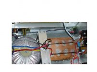
IMHO I found this had a significant impact on hum and dynamics when developing my prototype Aleph 2 construction.
Use a 1 - 2 millimeter copper sheet to terminate your capacitors, not wires.
This seems to work better than simply sheer capacitance which tends to crush the dynamics if you are not careful.
Terminate the star ground point a short disance from the central point of the capacitors using a short copper spur. this will reduce hum from the large charging currents.(aka D Self)
see the image below.....
2. Bias ...use heeps, makes a great foot warmer!
Up the bias as far as you dare, )make sure the current share remains 50/50%)it will sound sweeter.
3. Warmup..a given
Allow 1 hour warmup while consuming a good bottle of good Red.
4. Balanced inputs... a given
Always run balanced inputs for least noise and distortion from your BOSOZ or Aleph P.
5. Cables.
Try and run bi wiring direct from the ampifier outputs, just about every reviewer on the Planet says this will improve your sound.
Ian
1. Earthing.
IMHO I found this had a significant impact on hum and dynamics when developing my prototype Aleph 2 construction.
Use a 1 - 2 millimeter copper sheet to terminate your capacitors, not wires.
This seems to work better than simply sheer capacitance which tends to crush the dynamics if you are not careful.
Terminate the star ground point a short disance from the central point of the capacitors using a short copper spur. this will reduce hum from the large charging currents.(aka D Self)
see the image below.....
2. Bias ...use heeps, makes a great foot warmer!
Up the bias as far as you dare, )make sure the current share remains 50/50%)it will sound sweeter.
3. Warmup..a given
Allow 1 hour warmup while consuming a good bottle of good Red.
4. Balanced inputs... a given
Always run balanced inputs for least noise and distortion from your BOSOZ or Aleph P.
5. Cables.
Try and run bi wiring direct from the ampifier outputs, just about every reviewer on the Planet says this will improve your sound.
Ian
Attachments
most useful tip!
Uli
Coulomb said:Hello All, this is by far one of the most intruiging forums in a while on DIYAUDIO. 🙂
- - -> You´re definitely right!
Groups of FET's will change in test results over periods of time sometimes up and sometimes down. Most of the time it will be 2 or 3 doing the same thing, and this from FET's all the same date code.
- - -> Unfortunately I made the same experience. It costed me a
complete rebuild of my A2s.
Any feedback? Is this usefull or useless?
- - -> IMHO its the most useful hint!
Anthony
An externally hosted image should be here but it was not working when we last tested it.
Uli
BIas / Number of fets ?
When I read Nelson's comments on biasing, I start to thing about the right number of fets which should be used in a 100W Aleph-X. I understand that Nelson is using 16 per channel in his comercial products, I plan to use 12, but now it sounds like it is advisable to use only 8 per channel, so that they can be heavily biased ?
When I read Nelson's comments on biasing, I start to thing about the right number of fets which should be used in a 100W Aleph-X. I understand that Nelson is using 16 per channel in his comercial products, I plan to use 12, but now it sounds like it is advisable to use only 8 per channel, so that they can be heavily biased ?
"Hello Mark, I was wondering about a trimpot for R19 as a simple two connection variable resistor. Once I have found a value that appeals to me, I imagine it is best to replace the pot with a fixed resistor at that value?"
__________________________________________________
Anthony,
I also installed a pot in place but ended up ripping it out. I havd plenty of heatsinking to accomodate the extra heat. But you are right on the pot as you can tweek and keep an eye on the heat factor and not let it get out of hand. I think you will find that leaving the resistor out will give the best sounding results though....
Also I'm going to try bypassing the zeners and see what if any difference it makes. I'm going to use a 4.7uf bypassed with a .1uf film cap......
Mark
Anthony,
Was re-reading your post about testing FETs.....I wonder if you are testing way too long...I used 30 seconds for my tests and the voltage drop across all my source resistors is pretty close to each other as is the running temperature of each device. Also, is the power supply you are using very tightly regulated? It has to be to get repeatable readings on the devices.....I also used a Fluke 8502 5 1/2 digit DMM to read my devices. Tested mine twice(all from the same batch) and got pretty much the same readings..............?
Mark
Mark A. Gulbrandsen said:Anthony,
Was re-reading your post about testing FETs.....I wonder if you are testing way too long...I used 30 seconds for my tests and the voltage drop across all my source resistors is pretty close to each other as is the running temperature of each device. Also, is the power supply you are using very tightly regulated? It has to be to get repeatable readings on the devices.....I also used a Fluke 8502 5 1/2 digit DMM to read my devices. Tested mine twice(all from the same batch) and got pretty much the same readings..............?
Mark
Hello Mark thank you for the Feed back, I may indeed be running them to long as you say. I keep testing them until I get repeatable measurements, that's where I figure they will be when running over long oeriods in an installation. The one comment I have is that if we are lloking for groups within 30 mV, then IRF has got the N series production runs very tight. I say this because almost all the FETs I have tested so far are within 10 mV of each other regardless of testing variables. Whereas the older series FETs can be a lot further out.
I am using a regulated power supply that I check the output voltage on regularly during testing, it holds at 14.657. I am assuming that as long as all devices are tested at the exact same voltage, a few hundred millivolts below the specified 15 VDC is acceptabale as we are only looking for relative bias.
I am using a Fluke 8050A meter myself.
Anthony
Any feedback? Is this usefull or useless?- - -> IMHO its the most useful hint!
Thanks Uli.
Anthony
Re: BIas / Number of fets ?
Bagatelle:
I like EI's just fine, but for this application it seems that a gap in the magnetic circuit (a sawzall with a hacksaw blade works wonders) will be appropriate to keep the saturation down. In production we are using iron laminated bars. 2 mH or so seems to work just fine in all applications.
And yes, your full bodied reds are just what I like.
Run them between 25 and 50 watts at idle and keep them well heat sunk. Take my advice: don't ever exceed 50 watts on these 125+ wattage parts.
Keep in mind that you can raise the bias above the figure where r19 is open by sending a high value resistor off to a decoupled negative rail voltage. Easy to do, and doesn't significantly adjust the gain of the current source. One of the nice things about the setup on the Aleph circuit as produced is the separation between DC and AC parameters. You can adjust one without screwing up the other.


Bagatelle:
apassgear said:IMO the best inductor is an EI inductor though you will need a big one for 3 Amps say a 10 mH. this is way better than other types, provided is well design.
If you want to prize Nelson for his excellent designs send him a bottle or two of fine Cabernet wine.
I like EI's just fine, but for this application it seems that a gap in the magnetic circuit (a sawzall with a hacksaw blade works wonders) will be appropriate to keep the saturation down. In production we are using iron laminated bars. 2 mH or so seems to work just fine in all applications.
And yes, your full bodied reds are just what I like.
Blitz said:When I read Nelson's comments on biasing, I start to thing about the right number of fets which should be used in a 100W Aleph-X. I understand that Nelson is using 16 per channel in his comercial products, I plan to use 12, but now it sounds like it is advisable to use only 8 per channel, so that they can be heavily biased ?
Run them between 25 and 50 watts at idle and keep them well heat sunk. Take my advice: don't ever exceed 50 watts on these 125+ wattage parts.
Mark A. Gulbrandsen said:[BI was wondering about a trimpot for R19 as a simple two connection variable resistor. Once I have found a value that appeals to me, I imagine it is best to replace the pot with a fixed resistor at that value.[/B]
Keep in mind that you can raise the bias above the figure where r19 is open by sending a high value resistor off to a decoupled negative rail voltage. Easy to do, and doesn't significantly adjust the gain of the current source. One of the nice things about the setup on the Aleph circuit as produced is the separation between DC and AC parameters. You can adjust one without screwing up the other.
I would say that the fets are warming up during the test and so the gate threshold voltage is dropping. What I do when I want to match fets is lay them all on a slab of aluminium for a while before and during the test so that they are all at the same temperature, and so they stay at that temp during the test which is for about 5 seconds. Works great for me.Coulomb said:To put into numbers what I mean here is one example.
a FET measure 3.163 volts initially, after 30 minutes it measured 3.143 volts, after being off for an hour it came back on at 3.202 volts and gradually dropped to 3.170 volts. When I came back to lable it the next day and measured it for "one last time" it read 2.995 volts!!!

machting the fets
Hi,
How did I macht my 244 fets?
I tried to be close to there real utilisation, so PS 25V, current 0,8A
I let they warm up and made the measure after 10 mn, over this time I don't find a real difference ( I tried it about two hours), to be sure that my measures was correct I repeat the operation a second time an other day and find the same values (+/- 3mV), it was a long job.
Don't forget to put your 244 on a heatsink if you wish to use the same test.
Regards.
Re: Re: BIas / Number of fets ?
Last week I finished a pair of chockes built arround an M-15 EI-100 square core using AWG 16 magnet wire, and calculated a gap of 0.024" using Hanna's methode so I gapped the core with 0.015" since on an EI core we have double gaps (so 2 X 0.015") which should be good for 3 + Amps.
The final measurments are 16 mH and 0.21 Ohms DCR.
Haven't test them though. Since I allready have an CRC Pi filter on the Aleph 4, I was wondering if I left the actual filter and add the coils in the front to form a LCRC and maybe lower the R resistance from 0.8 to 0.4 or so just no to lower to much the rail voltages.
Any suggestions?
Nelson Pass said:Bagatelle:
I like EI's just fine, but for this application it seems that a gap in the magnetic circuit (a sawzall with a hacksaw blade works wonders) will be appropriate to keep the saturation down. In production we are using iron laminated bars. 2 mH or so seems to work just fine in all applications.
And yes, your full bodied reds are just what I like.
Last week I finished a pair of chockes built arround an M-15 EI-100 square core using AWG 16 magnet wire, and calculated a gap of 0.024" using Hanna's methode so I gapped the core with 0.015" since on an EI core we have double gaps (so 2 X 0.015") which should be good for 3 + Amps.
The final measurments are 16 mH and 0.21 Ohms DCR.
Haven't test them though. Since I allready have an CRC Pi filter on the Aleph 4, I was wondering if I left the actual filter and add the coils in the front to form a LCRC and maybe lower the R resistance from 0.8 to 0.4 or so just no to lower to much the rail voltages.
Any suggestions?
Circlotron said:
I would say that the fets are warming up during the test and so the gate threshold voltage is dropping. What I do when I want to match fets is lay them all on a slab of aluminium for a while before and during the test so that they are all at the same temperature, and so they stay at that temp during the test which is for about 5 seconds. Works great for me.
Hey there Circlotron, You know I just finished booking Beamtime on the Circlotron just south of Toronto, Canada in the Northern US. Any connection? 🙂
Anyway, my question is if my measurements are the most accurate, repeatable and stable after several hours of warm up, is that not the best result to use when Matching?
I have tried turn on, 30 secs, take reading and turn off, but the results are not as verifiable as my method. It seems the scientific process falls down in the "Time on" issue. As in any scientific process your test enviroment must be stable and constant, each individual FET could have a different "Instant on" reading due to junction temperature changes due to silicon impurities or specific densities. After all it is the properties of these very junctions we are trying to ascertain as being "Sympathetic" in Nature.
By leaving the FET's on for at least an hour, they all have ample opportunity to reach their individual states of equilibrium. This is where they can be bested tested for individual characteristics under the same repeatable conditions.
Thoughts on this, if you think it is VooDoo science speak up so our clan can identify you! 🙂
Anthony
Gate Source Voltage
BTW GS voltage rises with temperature 🙂)
as Mosfets have a negative temperature coefficient.
Uli
PS: I matched my IRF9620 to 1mV -> Result:
about 100 - 500mV output offset in my AXes.
I rematched them in situ -> Result: 10 - 20mV output offset.
BTW no caps in AX!😎 😎 😎
BTW GS voltage rises with temperature 🙂)
as Mosfets have a negative temperature coefficient.
Uli
PS: I matched my IRF9620 to 1mV -> Result:
about 100 - 500mV output offset in my AXes.
I rematched them in situ -> Result: 10 - 20mV output offset.
BTW no caps in AX!😎 😎 😎
Actually, if you examine a typical mosfet datasheet, you'll see that at low currents a mosfet typically exhibits a positive temperature coefficient and at higher currents it exhibits a negative temperature coefficient.
in situ
Hi Jarek,
"in situ" means to be put in the working amp.
Only there you have real life conditions.
Nobody wants the IRFs to be matched at 25°
but to be matched in their working environment!
I use IRF9620 instead of 9610 because I have
dozens of them and they are quite similar to 9610.
AND the have a higher transconductance thus
leading to more open loop gain -> better control
thru FB and better HF behaviour IMHO.
Uli

sorry
You need not excuse
We´re all amateurs in the best sense of this word:
We love this business!
Uli
You need not excuse
We´re all amateurs in the best sense of this word:
We love this business!
Uli
Missing something?
Said that I would report on the LCRC filter for the power supply on an Aleph 4.
was to lazy to check the inductors for power outside the amp so just connect them on the amp and "test" them.
To remind you (from previous post) this inductor is 16 mH wound with AWG 16 magnet wire on a EI 100 magnetic structure (M-15). Its gapped with a 0.030" spacer (2 X 0.015"). The DCR is only 0.21 Ohms.
The good news is that I got music, more transparent deeper soundstage, better midrange and highs, tremolos in voices are much clearer and better defined same as harmonics on instruments. Tracks that I regarded before as harsh are now more listenable.
The bad news is that my rails came down to 32V from 44V even though I lowered the R from previous 0.82 to 0.32 Ohms. Well this was quite unespected.
Even though I heard to music for about 20 minutes I can also say there seems to be less slam on the bass, but the amp was not yet at normal temperature.
I checked the temperature on the inductors and it was around 36°C, slightly higher than the tranies, but can say if they are working at saturation at this point. The only way to know for me would have to take them out of the amp and set them on some sort of setup to check them.
The question is, why did I get such a big drop on the rails???
Your input will be appreciated!!!!
You got such a big voltage drop because you changed the power supply from capacitor input to inductor input. When a capacitor is the 1st element after the bridge, you can expect the DC voltage to be something like 1.4 x VAC less losses. When an inductor is the 1st element after the bridge, you can expect the DC voltage to be something like 0.9 x VAC less losses. In practice, the voltage will steadily drop from 1 x VAC less losses down to 0.9 x VAC less losses relative to the amount of inductance you are using, you'll reach a stable 0.9 x VAC less losses at the point of critical inductance.
Hope this helps.
Hope this helps.
- Status
- Not open for further replies.
- Home
- Amplifiers
- Pass Labs
- Top ten ways to a better Aleph?