Adrian, take care of the transistor's pins orientation.
For example: if you use the BC550C, you have to flip it by 180°.
Best regards - Rudi
For example: if you use the BC550C, you have to flip it by 180°.
Best regards - Rudi
Thx. Just what I needed to know. I did buy some Sanken devices to have on hand, but will stick to the NJWs for this project.Rick, I do not recommend use the Toshiba 2SA1943 / 2C5200.
When the SYMASYM has been originally presented in this thread: http://www.diyaudio.com/forums/soli...ifier-designed-michael-bittner-our-mikeb.html
Pavel Macura experienced the SYMASYM to oscillate on its ouput, when he used the TOSHIBA output transistors.
He has been able to correct this error by using a different value for the NFB compensation capacitor.
The SYMASYM has been successfully tested with all kinds of OnSemi output transistors: MJL3281/MJL1302, MJL4281/MJL4302, MJW0281/MJW0302, NJW0281/NJW0302, MJL21194/MJL21193, ...
I am currently testing the SANKEN 2SC3263/2SA1294.
@Evette, Atupi, Potepuh, Arthur, IPolyakov: thank you for you money transfer.
I will send you the Builder's Manual, drill template, BoM, .... to your EMail adresses this weekend.
Best regards - Rudi
Rick
................The input pair are socketed BC550c and can be changed to other bce, or ecb, or gds (sk170) types...................
I already stated bce, ecb, gds.What is the difference in using 2Sk170 or bipolar MPSa18 or Bc550 ? Do i need to change anything else if i use one transistor or another ?
What more do you expect?
Not speaking of ways of connecting for is is obvious different semiconductor with different pinout. I was thinking about changing some rezistor value when using a Fet or bipolar. Is there any benefit using Fet instead of bipolar in the input stage ?
There are a few Designers that recommend jFETs for the input.
I have never compared a jFET input to a BJT input.
This may turn out to be my first comparison.
But I need a cascode to get a sensible Pq and Vds for the jFETs @ my voltages.
A little proto board already made up but it requires two extra connections to the PCB.
I have never compared a jFET input to a BJT input.
This may turn out to be my first comparison.
But I need a cascode to get a sensible Pq and Vds for the jFETs @ my voltages.
A little proto board already made up but it requires two extra connections to the PCB.
Adrian, take care of the transistor's pins orientation.
For example: if you use the BC550C, you have to flip it by 180°.
Best regards - Rudi
Hello Rudi.
I am an audio amp DIY enthusiast but have no technical background (economics). I studied electronics by myself and I think I have a good basic grasp. I have implemented several DIY projects – Rod Elliott P3A, Michael Bittner SymAsym – 5.3, Carlos DX, now I am on to Mihai Rauta RMI-FC100. I do them according to schematics – put them in Eagle, make the layout, etch the pcb – of course following the advises and suggestions posted in the threads. I will post some pics later when I finish the FC100 and give some of my listening impressions. Though, sometimes I do not entirely comprehend everything what is happening in the circuit, I have a lot of fun doing it. Thank you guys for your time keeping this site alive!
Recently I came across the thread opened 22nd April 2011, 11:47- SymAsym TO-3 and I thought to implement the project. I found the schematics and started to put it in Eagle using the Eagle SymAsym -5.3 version, as there are modification only in backend + cap multiplier and here I came across of a difference in original MikeB schematics and your schematic posted at the beginning of the thread regarding the connection of a 470uf electrolytic capacitor in the NFB(?) – in the original schematic (C19) the negative lead is connected to Q2 base (diffamp) in your schematic (C4) the positive lead is connected to Q2. In the schematic posted by Metal (nr5) C17 is connected negative to Q2 base and without an addition cap (c3). The v5.3 is working as I have constructed it, I am sure that the TO-3 is working too. I would like to understand why can this capacitor be connected both ways as it is a polar? Thank you for your time.
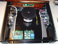
After having fixed the damage that arose due to the usage of too small fuses on the PCB (see my post #1089), I have proceeded with the build of my SYMASYM BB_Rev.2.
Well: it isn't a "Black Beauty - SYMASYM";the PCB's colour of my SYMASYM is green, and there are only of few of you that will have the adorable black PCBs.
I am using a 4x25VAC /400VA toroid with all "Schickimicki" (translated: "goodies", like full encapsulation, shielded wiring, ..., and which costs less than 2x225VA toroids) and have adjusted
the quiescent current of both channels, so that about 25mV drops across 2 adjacent 0R22 emitter resistors.
I am currently using 2 auxiliary PCBs in my build: my small PRE-PCB (doing source selection, LDR-based attenuation, Soft-Power-On triggering, ...) on the bottom left side and another PCB,
containing a "quick and dirty" PSU for the PRE, a DC mains filter and the Soft-Power-On circuit.
I have left some space beneath the transformer to install a small R-Core (if ever needed).
After completion of the internal wiring and verification of the functionality of my SYMASYM, I will add a "shielded 2nd floor" (above the 2 auxiliary PCBs and whatever PSU is needed else)
and will insert a RASPBERRY PI2 ModelB with associated DAC and WLAN access (via USB?) to be able to do "WLAN - music-streaming".
This is a ambitious project, I know, but I will take my time to implement it.
Best regards - Rudi_Ratlos
Attachments
Last edited:
The project is looking good Rudi. Can't wait to start on mine. I haven't received your parcel yet. 🙂 Rick
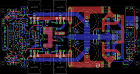
Rotundu, you are right: the NFB DC blocking-capacitor C4 (my naming convention) shall be rotated by 180°.
I have already informed the participants of the SYMASYM-BB groupbuy about this error in my layout.
The reason I did not notice in my prototype-build: the DC-offset is very small (nearly 0mV) and an electrolyt-capacitor normally allows several mV, if it is connected with reversed polarity.
Best regards - Rudi_Ratlos
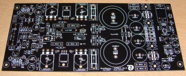
Received today the pcb's. They are very nice looking black pcb's
Thank you Rudi!
PS drill template and pcb is designed for Sanken 2sa/2sc transistors?
Thank you Rudi!
PS drill template and pcb is designed for Sanken 2sa/2sc transistors?
Adrian, you can use any TO3-P (for example: OnSemi NJW0, SANKEN 2SA/2SC, ...) and even TO264 - transistors.
I have included an image showing the BB-SYMASYM using TO264 - output transistors and have included the BB-SYMASYM_TO264 drill-template (if you like to have it).
The heatsink should be approx. 120mm long in case you are using TO264 transistors.
Best regards - Rudi
I have included an image showing the BB-SYMASYM using TO264 - output transistors and have included the BB-SYMASYM_TO264 drill-template (if you like to have it).
The heatsink should be approx. 120mm long in case you are using TO264 transistors.
Best regards - Rudi
Attachments
...................and there are only of few of you that will have the adorable black PCBs.
.........and mine arrived on Wednesday; I am late posting my thanks to Rudi because I was getting married again on Wednesday!
The boards are beautiful! Thanks again - and also the packing was first class.
SymAsym Oscilation.
Hello Andrew! and everybody Could you possibly answer how, if ever, can one determine or appreciate if the amp is oscillating without special instruments (oscilloscope?)? Thank you.
2nd Rudi PCB running.
With C7 = 33pF and C14 = 6p8F
I get the oscillation that Pavel described.
Turning down the bias to 20mV across the test points snubs it out.
Changed C7 to 47pF
The bias can be turned a little bit higher before the oscillation comes back on.
Touching the emitter lead of Q9 makes it worse.
Touching the base lead side of c14 makes it much worse.
I will do more later.
Hello Andrew! and everybody Could you possibly answer how, if ever, can one determine or appreciate if the amp is oscillating without special instruments (oscilloscope?)? Thank you.
Toshiba 5200/1943
Andrew I heard that you have a different of Pavel's, but elegant solution for Toshiba' SymAsym oscillation, could you please share it? Thank you.
Andrew I heard that you have a different of Pavel's, but elegant solution for Toshiba' SymAsym oscillation, could you please share it? Thank you.
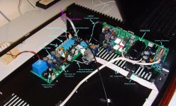
Dear SYMASYM-friends,
I have started and married the "Black-Beauty - SYMASYM" (which is in fact green in my prototype-case) with my auxiliary "DC-Mains-Filter, Soft-Power-On, Digital PSU - and RPre - PCB".
Everything works as designed so far, but I have to re-program the PIC-processor to be able to show all the information that it is able to show on a single 1x16 chars display.
"In my hunble opinion": I could not have this done better!
Best regards - Rudi_Ratlos
Attachments
- Home
- Group Buys
- TO-3 SYMASYM