Black beauties, partially build
Hello Rudi,
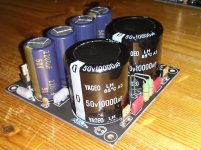
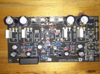
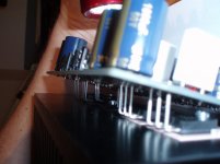
First images of the black beauties, I have to wait for the heat sinks, and some missing parts.
Reaching this state for one set of boards, 2 x PSU back-end and 2 x NJW Symasym boards took me about 6 hours.
It is again a real pleasure to stuff these boards, thanks again Rudi to make these available.
Grtz
Bert
Hello Rudi,
First images of the black beauties, I have to wait for the heat sinks, and some missing parts.
Reaching this state for one set of boards, 2 x PSU back-end and 2 x NJW Symasym boards took me about 6 hours.
It is again a real pleasure to stuff these boards, thanks again Rudi to make these available.
Grtz
Bert
Attachments
PCB's and package arrived
My package arrived today and the boards look beautiful!! I might mount some of them in a picture frame and hang it on my wall!!!😀
Many thanks to Rudi for the very smooth GB and the comprehensive documentation. Take care.
Those enclosures sure would be great for this AMP.🙂
My package arrived today and the boards look beautiful!! I might mount some of them in a picture frame and hang it on my wall!!!😀
Many thanks to Rudi for the very smooth GB and the comprehensive documentation. Take care.
Those enclosures sure would be great for this AMP.🙂
Need tip for C18 C19 type
Hi Rudi,
Can I have a tip on the type of Kondensator (GER), you had in mind for C18 and C19, you have specified 1µF for these, I did not find these on the BOM(Reichelt)
I have found this, based on the picture from the front page of the Build Guide,
MKT1818510065 Vishay / Roederstein | Mouser
Mouser-Teilenr.: 75-MKT1818510065
Hersteller-Teilenummer: MKT1818510065
Thanks in advance
Bert
Bert: your build looks good! Do not forget to solder a wire between the PAD labelled SignalGND (this is the "Small-Signal-GND" of the Frontend) near the MJE15031-driver and its counterpart near the Power-GND connector.
Capacitors C18 and C19 are not mandatory (especially not, if you use the onboard CAP-multiplier - which I really recommend to use!).
Either take a X7R-2,5 100N from Reichelt or a 1µF MKT.
Take care, when you insert the output-transistors, the drivers and the TEMPCO BD139!
Drill the holes into the heatsink and tap them; cover the holes with silicone insulating foil, bend the 7 transistors' legs accordingly and insert them from beneath the PCB.
Fix the transistors slightly with metal screws and use your distance sleeves to obtain the correct height of the PCB. Then fix the transistors tightly.
Measure the resistance all of the 7 transistor's legs with respect to the heatsink. There may not be any resistance!
Then fix the transistors with some solder-points on the PCB's component-side, unscrew them all and solder them from the PCB's solder-side.
Maybe that I am repeating myself.
I myself - when I built the prototype - have not done it as written before, and the result has been a very small, nearly unvisible gap between the drivers and the BD139 and the heatsink.
I have had a lot of problems thereafter during the quiescent-current adjustment phase (thermal runaway problems!), until I finally saw my problem.
So: do it slowly!
Michael: I am glad to hear that my small parcel arrived safely!
Best regards - Rudi_Ratlos
Rudi, Thanks explaining thisCapacitors C18 and C19 are not mandatory (especially not, if you use the onboard CAP-multiplier - which I really recommend to use!).
Either take a X7R-2,5 100N from Reichelt or a 1µF MKT.
Drilling and tapping day
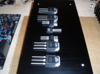
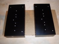
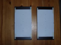
Hi, today was drilling and tapping day.
about 4,5 hours to reach the state shown in the pictures.
1, drill template.
2, punched.
3, drilled and tapped.
4, PCB mounted, no transistors.
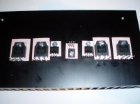
5, transistors mounted.
On the last picture the 15030/15031 might be reversed, I will need to check this tomorrow.
Yes I know, there is no insolation foil between the transistors and the heat sinks, that will be done on the final mount.
Also some zoomers might notice that not all transistors have the insulation washers installed, will also be done on final mount.
In this state, I did want to check if it all fits, yes it does, however be aware to use flathead screws to mount the transistors, using allen / inbus (GER) screws does not work, these are too high.
Thanks for the drill template Rudi, this little pease of paper saves a lot of time.
When time permits, tomorrow could be the first listening test
Grtz
Bert
Hi, today was drilling and tapping day.
about 4,5 hours to reach the state shown in the pictures.
1, drill template.
2, punched.
3, drilled and tapped.
4, PCB mounted, no transistors.
5, transistors mounted.
On the last picture the 15030/15031 might be reversed, I will need to check this tomorrow.
Yes I know, there is no insolation foil between the transistors and the heat sinks, that will be done on the final mount.
Also some zoomers might notice that not all transistors have the insulation washers installed, will also be done on final mount.
In this state, I did want to check if it all fits, yes it does, however be aware to use flathead screws to mount the transistors, using allen / inbus (GER) screws does not work, these are too high.
Thanks for the drill template Rudi, this little pease of paper saves a lot of time.
When time permits, tomorrow could be the first listening test
Grtz
Bert
Attachments

No sound today
I just found out (too late for one channel), by re-checking the transistor positions on the heat sink, that I messed up the positions of the NJW transistors, for one channel. (I did not pay attention to how Rudi packed the matched transistors, ( I do have two sets, my mistake ))
I was all discovered before putting power on anything, so no harm done.
But it means I have to desolder the transistors for one channel, and that will take some time.
Mounting the board on the transistors is very doable, it did remember me of playing the micado game 🙂 as Rudi wrote before, be patient.
Please ignore the last picture in my previous post, that one is completely wrong.
Grtz
Bert
last picture is wrong
Please ignore the last picture.
Bert
Not only the 15030/15031 where reversed, also the NJW's are positioned wrong.5, transistors mounted.
On the last picture the 15030/15031 might be reversed, I will need to check this tomorrow.
Please ignore the last picture.
Bert
some micado tricks
Hello again,
De soldering was not possible, so I had to butcher (cut off the leads) the transistors, after that, with a desoldering pump and some desoldering wick, the PCB was clean to start mounting the second set of transistors.
To build the second set I have to wait until the NJW become available again, first quarter 2015 according to Mouser.
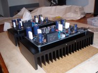
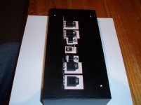
From the pictures you can see I have used kerafoil, to insulate the transistors from the heat sink.
Two little trick's to make mounting the PCB on the transistors easy:
1. Place the heat sink on the side with the legs of the BD139 nearest to the work surface, start by placing the PCB on the BD139 transistor legs first, then place the PCB over the NJW transistor legs.
2. Get your self a LED pocket torch (taschenlampe (GER)), and illuminate the PCB from the component side near the holes of the MJE transistors, the light will shine through the holes of the MJE transistors, and will make positioning the legs a peace of cake.
I tried to illustrate this with the third picture.
No sound today, after yesterday setback I became a little more careful, and I will wire up next weekend.
happy buliding
Bert
Hello again,
De soldering was not possible, so I had to butcher (cut off the leads) the transistors, after that, with a desoldering pump and some desoldering wick, the PCB was clean to start mounting the second set of transistors.
To build the second set I have to wait until the NJW become available again, first quarter 2015 according to Mouser.
From the pictures you can see I have used kerafoil, to insulate the transistors from the heat sink.
Two little trick's to make mounting the PCB on the transistors easy:
1. Place the heat sink on the side with the legs of the BD139 nearest to the work surface, start by placing the PCB on the BD139 transistor legs first, then place the PCB over the NJW transistor legs.
2. Get your self a LED pocket torch (taschenlampe (GER)), and illuminate the PCB from the component side near the holes of the MJE transistors, the light will shine through the holes of the MJE transistors, and will make positioning the legs a peace of cake.
I tried to illustrate this with the third picture.
No sound today, after yesterday setback I became a little more careful, and I will wire up next weekend.
happy buliding
Bert
Attachments
Last edited:
I see someone is selling njw transistors http://www.diyaudio.com/forums/swap-meet/261904-fs-semi-transistors-mjl4281-4302-njw0302-0281-a.html
Hi Rudi,
I used your BOMs 7 days ago at Reichelt and the parcel arrived today. Its all been so pleasantly easy .
But the pressure is on. You've done all the work so far. Now its up to us to make all these amps a reality.
I used your BOMs 7 days ago at Reichelt and the parcel arrived today. Its all been so pleasantly easy .
But the pressure is on. You've done all the work so far. Now its up to us to make all these amps a reality.
Paul: I hope that you are learning from the errors that Watchtmouse has done! 🙂
Best regards - Rudi
Best regards - Rudi
Oh yeah. As I was reading Wintermouse's report, it reminded me of the many times I have connected things the wrong way round . But its great that W'mouse has published this. Its obviously a critical step and not one that is easy to reverse.
Wanted to share my progress too. I like it, when people start populating their boards and you can see progress 🙂
Though, I did not yet order any parts yet. There are still 2-3 unfinished projects currently running, so I stuffed my boards with parts I still had. And as I already have a pair of Symasyms up and playing music, I am not in a hurry.
![URL]](/community/proxy.php?image=http%3A%2F%2F%5BURL%3Dhttp%3A%2F%2Fwww.directupload.net%5D%5BIMGDEAD%5Dhttp%3A%2F%2Fs7.directupload.net%2Fimages%2F141002%2F4r5eshko.jpg%5B%2FIMGDEAD%5D%5B%2FURL%5D&hash=c867ab63944524ae847b6fe42129e1ed)
As I said, after my first Symasyms, I will try to choose higher-end, but still affordable (so no boutique) parts for my build. Resistors will be Dale RN60D through the build, must say its going to be a tight fit, but hey, who doesn't like it tight ;-) . The 2W and 3W wire resistors being Mills or Vishay CPF series. For the 0.22R 5W resistors I will try out something different and use those little cuties
Not yet quite shure about the capacitors yet. For some spots, I will need to measure the maximum mountable diameter. As its already rather tight with may 100nF Vishay Roederstein MKP1837 PP caps, I will have to check for that after all small parts are soldered. It will be a somewhat "The Black Beauty Lego Symasym".
Will keep you updated! Thanks again Rudi, for making this really beautiful and fun project become reality.
Regards,
Fabian
Though, I did not yet order any parts yet. There are still 2-3 unfinished projects currently running, so I stuffed my boards with parts I still had. And as I already have a pair of Symasyms up and playing music, I am not in a hurry.
As I said, after my first Symasyms, I will try to choose higher-end, but still affordable (so no boutique) parts for my build. Resistors will be Dale RN60D through the build, must say its going to be a tight fit, but hey, who doesn't like it tight ;-) . The 2W and 3W wire resistors being Mills or Vishay CPF series. For the 0.22R 5W resistors I will try out something different and use those little cuties
An externally hosted image should be here but it was not working when we last tested it.
mounted on a heatsink. Probably they will get one long and big heatsink on the component side fixed with clips, somehow similar to the system used in the Paradise R3 phono stage.
Not yet quite shure about the capacitors yet. For some spots, I will need to measure the maximum mountable diameter. As its already rather tight with may 100nF Vishay Roederstein MKP1837 PP caps, I will have to check for that after all small parts are soldered. It will be a somewhat "The Black Beauty Lego Symasym".
Will keep you updated! Thanks again Rudi, for making this really beautiful and fun project become reality.
Regards,
Fabian
Last edited:
Gentlemen, warning. I have just opened the box from Reichelt. Inside are the components as ordered. Also inside is a free, 1200 page, illustrated, colour catalogue , full of goodies you need and want , and full of goodies you don't need and want.
Anybody in need of a Preamp? As I never finished and no longer need my VCPre (sorry Rudi) I am selling mine.
Included would be the
- VCPre PCB
- 2x16 Char LCD, soldered to the LCD auxilliary PCB
- Motor Potentiometer (will have to look up the brand, but it was the one Rudi recommended)
- IR Receiver and temperature ICs
- Cable housings to complete the cables for the VCPre
You would only need the LDRs to complete it.
If anybody is interested, just contact me and we will a suitable price.
Regards,
Fabian
- Home
- Group Buys
- TO-3 SYMASYM