No, I get the 16VDC when the Symasym is not connected..on BOTH protect boards...
I think it is coming from the "ground" of the protect board maybe? To each board I have connected one of the secondaries of the power transformer. That is the only way I can get at least 24V to the regulator. I think...Since I have one of the AC legs connected to the ground of the speaker protect board could that be where the 16VAC is coming from? From the schematic it looks like a plausible explanation.
I think it is coming from the "ground" of the protect board maybe? To each board I have connected one of the secondaries of the power transformer. That is the only way I can get at least 24V to the regulator. I think...Since I have one of the AC legs connected to the ground of the speaker protect board could that be where the 16VAC is coming from? From the schematic it looks like a plausible explanation.
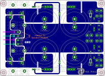
Carl, you use a transformer with 2 secondary windings, pink and turquoise, rated a 25VAC each.
One line of each secondary winding connects to "GND".
Connect the 2 orange coloured wires to the Speaker Protect PCB.
(In effect you are connecting a secondary winding to the Speaker Protect PCB).
Connect the orange AC-line to the top pole of the 2-pole power connector of the Speaker Protect PCB and the AC / GND - line to the bottom pole of the connector.
You should never have any AC voltage on the AMP-connector of the Speaker Protect PCB, if the PCB is not connected to the AMP.
Best regards - Rudi
Attachments
If Cj had did what he was told and not connect the protect PCB, then we would have one set less of confusing reports.
Cj,
you are not helping yourself.
Cj,
you are not helping yourself.
I agree, Andrew.
Carl: forget about the Speaker Protect PCB for a while, please!
Do not connect it at all!
Rudi
Carl: forget about the Speaker Protect PCB for a while, please!
Do not connect it at all!
Rudi
I know...my ADD got the better of me....
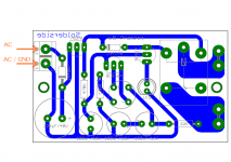
So I think I know what the problem is...my PSU board is different from the one Rudi laid out.
I do not see a connection scheme that will work here...at least not an obvious one. I am pretty sure that using both legs of one secondary in the speaker protect pins and then grounding the "ground" one would be bad right?
Attachments

Success!!!! It must have been one or more of the transistors.
I am now running both channels per specification.
Now I just need to figure out a speaker protect scheme....
Thank you all for your suggestions....and patience....
I am now running both channels per specification.
Now I just need to figure out a speaker protect scheme....
Thank you all for your suggestions....and patience....
Carl: unbelievable!
The speaker protection scheme in your case: connect +Vcc (about 35VDC) of your PSU to the "AC-pole" of the 2-pin Speaker-Protection-PCB-connector and your PSU-GND to the "AC/GND - pole" of the Speaker-Protection-PCB - connector.
This way: you will have a Power-On delay, you will of course have DC-protection, but you will not have immediate shutdown of the speakers, when you turn power off (because of the reservoir cap's discharging).
Maybe this will introduce some "Hiiiiiiiisssss, SSssssssccccchhhht", when you switch off the mains, but this will definitely not hurt your speakers.
Best regards - Rudi_Ratlos
Last edited:
Wow!
Tonight I rewired the speaker protects per Rudi's post above and worked like a charm. The relays engage after about 5 seconds and then disengage after 3-4 seconds upon power off.
I just need to get some more fuses and I can put the top on.
I am listening via a 5687 Aikido pre amplifier and everything is very quiet, sound is transparent much like my old Yamaha ca-810.
One question...if I have enough heat sink what is the harm to crank up the bias more?
I have been enjoying SYMASYM all weekend with no issues.
Thank you again for all your patience and suggestions. The Aikido pre amp is a perfect match and the combination works well together.
I look forward to having all the caps break in which can only improve upon what is already an extremely good sounding amp.
Thank you again for all your patience and suggestions. The Aikido pre amp is a perfect match and the combination works well together.
I look forward to having all the caps break in which can only improve upon what is already an extremely good sounding amp.
What tube complement are you using in your Aikido pre amp? I ask, because I'm still looking for the 'right' combination when feeding a solid state amp, such as the Symasym (currently under construction for me.)
Thanks,
Ryan
Thanks,
Ryan
My Aikido preamp is 6CG7 input with 5687 output. It is a dedicated 5687 output board but the inputs are interchangeable with similar like 6dj8, 6922, 6n1p etc...
The 6CG7 is lower gain of around 10 which works perfectly.
Coupling caps are Auricap 0.68uF bypassed by Russian PIO 0.22uF.
The 6CG7 is lower gain of around 10 which works perfectly.
Coupling caps are Auricap 0.68uF bypassed by Russian PIO 0.22uF.
Hi Rudi,
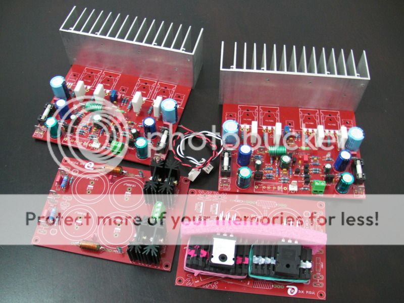
PCB's already populated and waiting for few parts from Farnell, please let me know if the heatsinks shown here are adequate or not. cheers.
Thanks in advance,
Junie
PCB's already populated and waiting for few parts from Farnell, please let me know if the heatsinks shown here are adequate or not. cheers.
Thanks in advance,
Junie
Junie, the heatsinks are adequate.
Best regards - Rudi
P.S.: Wishing you success with your SYMASYM!
Best regards - Rudi
P.S.: Wishing you success with your SYMASYM!
Last edited:
Thanks Rudi.
I will keep you posted on my progress. regarding the input trannies, Jfet is unobtanium here in dubai you mentioned that any low noise trannies will do the job but which one is favorable as your "CHOICE"?
Regards,
Junie
I will keep you posted on my progress. regarding the input trannies, Jfet is unobtanium here in dubai you mentioned that any low noise trannies will do the job but which one is favorable as your "CHOICE"?
Regards,
Junie
I have been running symasym now for many days. I was tracking down a buzz that I eventually traced to my source. In doing so I plugged in my Moskido power amp - Aikido front end with a single pair of BUZ901/BUZ906 MOSFETS per channel in class A. The amp runs at 26V and 1.25A per channel.
What I noticed was that the bass on the Moskido goes much deeper. Now both amps sound amazing and are silent - it is just that I think I like the bass out of the Moskido better.
Are there different values of maybe the feedback cap and resistor to try and see if bass gets more to where I like it? Current values are 10pF and 22K.
Also I have increased R36 to 1K to reduce the gain a little due to my preamp.
To reiterate, I am not unhappy with the result, I would just like to explore how to change the bass more to my liking.
- Home
- Group Buys
- TO-3 SYMASYM