Hi!
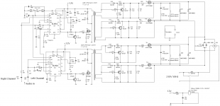
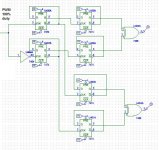
Through last year I've done some experiments with plasma speakers, so i decided to make a stereo version for my high school project. I've made the schematic based on this plasma speaker.
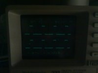
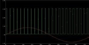
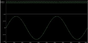
I have serious problems with the modulation section. At first i would like that the flip-flops on IO1 and IO2 are working asynchronously as shown on attached image. I'm using the flip-flops to limit duty cycle to 50%. When i turn on the modulation section it's random whether the flip-flops are running synchronous or asynchronous! This fact is making serious problem for the power section, the transformers in synchro will make huge peaks. I don't know if TL494 is capable for doing this, but i hope it can.😕
The second problem is if the T3 and T4 are switching load (even a dummy 15Ohm resistance load!) it sometimes disables the flip-flop function! So it doubles the frequency, the GDT cannot handle such high duty-cycle and the power section blows. I haven't found any rule when it occurs but it depends on the duty-cycle and frequency. However it's also random on which TL494 this occurs. I've detected one frequency when it doesn't depend on the duty cycle and everything works OK.
ΔV ripple of 12V source on switching single 15ohms is about 0,8V, maybe the problem is in source, but when I've changed C41 (100uF filter) to 1mF or 10mF it didn't fix the problem 🙁
I've looked on gate drivers which can stop DC coupling on GDT, but there are hard to obtain in shops here.
Although the modulation section works poorly, the sound from tweeter is great!
Thank you for help
Through last year I've done some experiments with plasma speakers, so i decided to make a stereo version for my high school project. I've made the schematic based on this plasma speaker.
I have serious problems with the modulation section. At first i would like that the flip-flops on IO1 and IO2 are working asynchronously as shown on attached image. I'm using the flip-flops to limit duty cycle to 50%. When i turn on the modulation section it's random whether the flip-flops are running synchronous or asynchronous! This fact is making serious problem for the power section, the transformers in synchro will make huge peaks. I don't know if TL494 is capable for doing this, but i hope it can.😕
The second problem is if the T3 and T4 are switching load (even a dummy 15Ohm resistance load!) it sometimes disables the flip-flop function! So it doubles the frequency, the GDT cannot handle such high duty-cycle and the power section blows. I haven't found any rule when it occurs but it depends on the duty-cycle and frequency. However it's also random on which TL494 this occurs. I've detected one frequency when it doesn't depend on the duty cycle and everything works OK.
ΔV ripple of 12V source on switching single 15ohms is about 0,8V, maybe the problem is in source, but when I've changed C41 (100uF filter) to 1mF or 10mF it didn't fix the problem 🙁
I've looked on gate drivers which can stop DC coupling on GDT, but there are hard to obtain in shops here.
Although the modulation section works poorly, the sound from tweeter is great!
Thank you for help
Attachments
Last edited:
Are you driving push pull with the flip flops inside the TL494?
I think yuo re getting your 50% by not using one set of pulses (one o/p txr is open)
It is difficult to avoid DC coupling if you plan to use the forward converter. The transformer may saturate if driven with standing DC.
Try to use a Half Bridge Driver like IR2110 or LM51xx.
I think yuo re getting your 50% by not using one set of pulses (one o/p txr is open)
It is difficult to avoid DC coupling if you plan to use the forward converter. The transformer may saturate if driven with standing DC.
Try to use a Half Bridge Driver like IR2110 or LM51xx.
Last edited:
Yes, I'm driving push-pull with flip flops inside and I'm not using one set of pulses. However the transformer saturates only when the flip flop is oddly disabled.
I have just found that is not possible to make internal flip-flops run always asynchronously 🙁 Does anybody know how to do it by using external flip-flops?
I have just found that is not possible to make internal flip-flops run always asynchronously 🙁 Does anybody know how to do it by using external flip-flops?
What you do by using these flipflops is simply alternate the pulses of the PWM.
It is merely an odd-even flow splitter. I think it ll be enough you pick up the circuit inside TL494 from its functional diagram.
Is it enough if you re able to split the PWM somehow to make the duty cycle 50% outside the TL494?
Here is how you do it outside the controller.
This circuit drops both freq and duty cycle to half of what it was before entering the circuit.
Now, is that what you needed?
Attachments
Last edited:
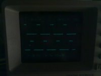
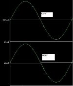
Unfortunately no 🙁 I have to alternate pulses from IC1 and IC2 . The alternated pulses must be asynchronous (left and right) as shown on the second image. I have to guarantee it, but don't know how. I think this schematics based on internal schematic of TL494 will make the same synchronization problem. The first pulses are making synchronization 🙁
Attachments

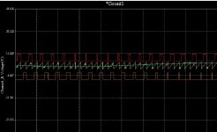
This simulation should be better. This is how I want it to work.
However it doesn't fix the problem with synchronization - first pulse combined with soft-start is killer. Damn, maybe the problem is in special soft start for each IC... And on the second IC i should use the opposite output(C2 E2).
However it doesn't fix the problem with synchronization - first pulse combined with soft-start is killer. Damn, maybe the problem is in special soft start for each IC... And on the second IC i should use the opposite output(C2 E2).
Attachments

Last edited:
I dont actually understand how you get two PWMs.
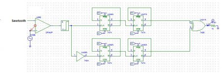
Anyway a circuit that will alternate pulses is here. This is not based on TL494 internal. This circuit splits the PWM into two phase modulated signals and divides them in frequency and then combines them to form a PWM with alternating duty and half frequency.
So is the previous one. I think this wont have even a problem with delay because both signal paths are likely to be matched very well.
Attachments
Each TL494 is modulating his audio signal. Sawtooth used for modulation is synchronized. And the pulses from IC1 have to be asynchronous to IC2.
Ok ok. got it
The two channels in a stereo system are usually considered independent.
The uncertainity that you see while turn on is merely dependent on the actual signals that re applied at inputs.
But it is possible to adjust so that the pulses dont overlap by providing suitable DC offsets to the Left and right channels.
Try this.
Left channel => 0.33* left audio + 66% Vcc => PWM1
Right channel => 0.33* right audio -66% Vcc=> PWM2
I mean they should look like this when DC coupled and use the same ramp for both:
Irrespective of signal content in channels PWM1 and PWM2 wont NOT overlap at all 🙂
Attachments
Last edited:
The signals are already DC coupled to the center of sawtooth by the trimmer duty cycle. There were no audio signal on the pictures at the top. The "signal" was just the center DC. You get it wrong, but that's because my bad English, or for something that I didn't tell, sorry for that.
However the signals couldn't be synchronous or totally independent, the HV-transformers are making peaks. Two united spikes from them can be fatal.
However the signals couldn't be synchronous or totally independent, the HV-transformers are making peaks. Two united spikes from them can be fatal.
See if you have additional DC on these channels you ll never overlap th resulting PWMs because its the voltage that causes the pulses to widen / narrow.
So if you are restricting a signal to a particular voltage regime, pulses would occupy a corresponding time frame only.
Try modulating as I said. Same circuit as before. But signals with additional DC as shown. Thats all.
And, without signal, the left channel should be 0.33 Vcc and right should be 0.66* Vcc.
And as far as my knowledge goes, this should be the only (easy) way of locking PWM pulses within a time frame.
Last edited:
Well I don't get how this DC coupling can help. On which circuit?
The internal TL494 comparator reduces the maximum width of pulse to 95%, and there is always some minimum pulse. So it will always make pulse that can be handled by Flip-Flop.
Or I don't get what you're talking about 🙁
The internal TL494 comparator reduces the maximum width of pulse to 95%, and there is always some minimum pulse. So it will always make pulse that can be handled by Flip-Flop.
Or I don't get what you're talking about 🙁
See leave the TL494 alone for sometime. 🙂
Use you simulator LTspice or whatever. Try the circuit you ve shown in post #7 with DC on both channels and see if its alright.
The signals should look like in post#10.
Meanwhile I would like to confirm if this is what you want.
1) You have left and right channels (independent) and hence 2 PWMs.
2) Yet you want these two PWMs to be alternately pulsing.
3) This should happen even with audio at your inputs.
Am I right?
Last edited:
Try to make your left and right channels look like what is shown in #10.
You ll get it dont worry. Once you get it you ll understand the logic behind it.
You ll get it dont worry. Once you get it you ll understand the logic behind it.
Its this change in DC that holds the pulses from overlapping. #10 has both signals shown simultaneously. 0.5 Vcc is the center of the plot.
Right and left channels are offset above and below so that they dont clash that is they dont occupy the same voltages, no matter what information (music, noise, anything else) they carry.
And dont use flip flops use an ordinary sine-triangle PWM setup as the splitting comes automatically.
Right and left channels are offset above and below so that they dont clash that is they dont occupy the same voltages, no matter what information (music, noise, anything else) they carry.
And dont use flip flops use an ordinary sine-triangle PWM setup as the splitting comes automatically.
Last edited:
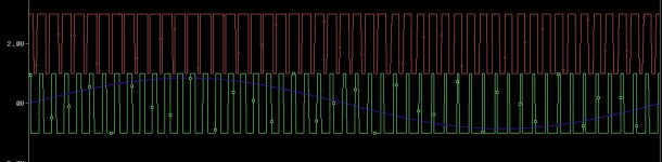
I have simulated the circuit. Pls see picture.
Just try it. For further modifications on pulse position, try inverting one of these signals.
Interleaving of pulses. I think you re trying to get away with a less dangerous circuit by having these signals interleaved.....
Am I right?
Just try it. For further modifications on pulse position, try inverting one of these signals.
Interleaving of pulses. I think you re trying to get away with a less dangerous circuit by having these signals interleaved.....
Am I right?
Attachments
Last edited:
- Status
- Not open for further replies.
- Home
- Amplifiers
- Class D
- TL494 based plasma tweeter