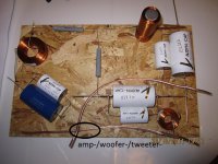
Ok I think I have it, I hope the coils are not disturbing eachother!
I should probably turn the left coli 90 degrees and lay the big one down.
See picture..
The others were better IMO (with respect to the coil placement). yes the left coill should be turned 90deg then it should not cause issues. if you have them in their original positions AND turn the left one on its side and at 90 degrees then the chances of interference will be virtually nill 🙂 however even at fairly close quarters with the coils at 90 degrees to one another (rule of thumb you should not be able to see another coil through the hole of a coil) then they should be ok.
My recent crossover has the coils quite close together. Troel's indicates (in his experiments) that 20cm centre to centre is enough spacing even if mounted in the same orientation.
Tony.
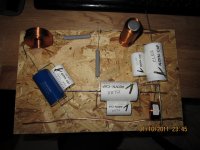
Ok, I have not soldered it together since I had a problem with it beeing too tight. You prefer this one (pic)? The only bad thing is I need 2 wires to connect it with. But I can use the same layout and put the components a little closer to eachoter and using you coil orientation advise. And I will lay the big one down west-east to make it more secure to the board.
Attachments
Last edited:
oh I only just realised the tall thin thing is a coil, I thought at first it was an electrolytic cap 😉 I think you should be fine with that coil orientation. just for reference, here is a link to Troels test's on coil orientation, at the end it shows the recommended placements. Placement of coils in crossover networks
Tony.
Tony.
Yeah I will glue it into place and solder it tonight, I spend too much time thinking about this, but ok it is my first time doing it so...
Thanks wintermute, I have looked at it for help.
Thanks wintermute, I have looked at it for help.
I drill the wooden boards and fix with tie wraps in such cases. 2 pairs of holes along a big pp cap axis fix it pretty well. Because something maybe changed to taste later.
Thanks for your concern Salas, I will use a glue that is flexibel and can be removed with a sharp knife. Troels Gravesen uses the same (Placement of coils in crossover networks) on this site. And yes I will go easy with the glue using only so much needed, the big coil needs rather much I guess but otherwise it will be small amounts.
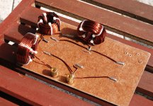
I too used cable ties for attaching my coils (and caps) to my crossover board. The vertically mounted coils I only used a single one. They are not that sturdy, but they aren't going to fall off either 😉 Cable ties are quite strong! you can see fairly well in this pic of the partially constructed crossover. The link I posted earlier has the fully completed board where you can see the cable ties on the caps as well.
Black cable ties are the ones holding to the board, white ones are the ones I used to hold the coils together after I wound them.
Tony.
Black cable ties are the ones holding to the board, white ones are the ones I used to hold the coils together after I wound them.
Tony.
Attachments
Tony, that looks nice, but I am too lazy right now and getting eager to hear them play, so I will just use a little glue so I can move the board and start playing. Easy to remove with a razor blade knife. I really like the looks of my white capacitors and I do not think that glue of mine will destroy them in any way, it is rather flexible.
Yes it is, it is a little simpler cap compaired to the rest, the white ones do not exist in that big capacitance value. But it is the same type of capacitor, not bipolar. http://www.europe-audio.com/Product.asp?Product_ID=8501
The white ones are bigger, for example the 10uF is bigger than the blue Jantzen 33uF as seen in my pictures.
The white ones are bigger, for example the 10uF is bigger than the blue Jantzen 33uF as seen in my pictures.
Last edited:
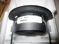
Normally the wider lug is positive. If you will use a 1.5V battery cell on the driver and you will watch from the side, you will see the dome move slightly out when (+) is connected the right way.
Ok, the terminals looks to be the same size to me, so I will try the battery test.
I have glued the crossover but it need to dry so the soldering will be done tomorrow 🙁. I also discovered I did not have a wire cutter (forgotten at work) to remove excessive wire so I will relax tonight and complete it tomorrow.
One question Salas, I have read somewhere that when haveing a second order butterworth filter (which your filter reminds me of) + and - should not be the same for woofer/tweeter. Did you try this?
That's textbook analysis for electrical, no acoustic slope phase or Z plane emitting distances taken into account. If you will reverse polarity you will get some null in this one. If the terminals are same width then the mark (any color) should be (+) logically, but do the battery test for the sake of sanity.
The filter is ready (se picture), next step after dinner is to solder some connection cables, put some stuffing in the cabinets just to start with and insert the reflex port. It is safe doing this right? I know it will not be 100% sealed everywhere since I got a removable baffle with wooden plugs, but I can´t damage anything right?
Attachments
- Status
- Not open for further replies.
- Home
- Loudspeakers
- Multi-Way
- "Tired2way" speaker building.