Huh, 10% and 10% SMPS, and this is an optimistic scenario. Actually, I just back from one interesting factory for super-fine-metal-mesh production(I saw their show-room with B&O, B&W samples). One my neighbor, englishman, recommended me to take a look. I think I could use such mesh at front panel for the best ventilation(currently I have vents on the bottom steel sheet panel) and it looks great, yes, just great. But I'm not sure if I ready for such brave ID step yet. I'm really haven't any experience regarding Industrial design before, so I need any aside opinions as an air 😉
I really feel that the idea to split an integrated amp to amp and external SMPS it's kinda moron's decision.
+1
Of course we know why it is but it still is stupid especially when the 5.5 mm round plugs are used.
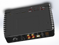
How does the bottom plate looks like and where does the "cold air" comes into the case to have an optimal chimney effect to cool the modules.
me too, that's why I had fine-mesh factory trip today. However, such a compact design couldn't be optimal, rather compromise. doctormord, if you have a better idea, you are welcome.
Best way would be a thermal (FEM) analysis. Autodesk Fusion 360 can do that but i don't know if a fluid module is needed for this. I only did structural and thermal conduction analysis.
Before getting the chassis done, a 3d-printed mookup might help to see thermal hotspots. It's also a good idea to have the PCB mounted on the bottom side. Have you checked temperatures with a thermal imager before?
Before getting the chassis done, a 3d-printed mookup might help to see thermal hotspots. It's also a good idea to have the PCB mounted on the bottom side. Have you checked temperatures with a thermal imager before?
Or have the whole bottom made with more cooling slots like the ones already there, build the prototype and measure. I think you will have to derate the output power.
One doesn't need fancy software to see 60W dissipation won't work in such a small casing 🙂 Like you said: it is a size/output power compromise and not many will go full throttle with such a nice device.
One doesn't need fancy software to see 60W dissipation won't work in such a small casing 🙂 Like you said: it is a size/output power compromise and not many will go full throttle with such a nice device.
Last edited:
Well then you did not understood my point of view. It's not about proviing whats not working at all, it's about knowing how it is working best with least derating and proper thermal path management.One doesn't need fancy software to see 60W dissipation won't work in such a small casing
But yeah, there are several ways to get the job done.
Without knowing the thermal hotspots and bottlenecks prototyping will be less efficient.
Last edited:
I was just kidding. IVX has a dream and I think nothing will stop him from building a fancy small FDA with V8 power and built in PSU (applause!!!) 😀 Efficiency does not seem to harm the processes. On the contrary, the device would probably not have been designed and prototyped if efficiency was a goal.
Although passive cooling would seem the ideal solution I guess a small fan will be necessary to get rid of 60W and/or overheating. Also ventilation slots will be necessary at the upper cover. Better derate output power and keep it simple IMO (so passive). A diecast aluminium casing would be premium. If standoffs are incorporated in the design then heat will be transferred directly to the casing. Needs careful planning and design though. Today I noticed such diecast casings are now being produced for RPI 3B+.
Although passive cooling would seem the ideal solution I guess a small fan will be necessary to get rid of 60W and/or overheating. Also ventilation slots will be necessary at the upper cover. Better derate output power and keep it simple IMO (so passive). A diecast aluminium casing would be premium. If standoffs are incorporated in the design then heat will be transferred directly to the casing. Needs careful planning and design though. Today I noticed such diecast casings are now being produced for RPI 3B+.
Last edited:
jean-paul, I'll not reduce rated power for sure. I'm going to limit the time for max power, I have 2 NTC sensor, one on primary SMPS side, another one on the secondary side. First one will stop SMPS if trafo temperature reach 110C, the second one will reduce DSP limiter settings to -3db if PCB surface will be dangerously hot. Please note that both case, in fact, impossible with music listening, only if long-term sine on resistor load.
Derating is not reducing. Let's say that a device can put out 200W but when doing this for an hour internal temp is 90 degrees. Then tests and measurements can indicate that while being able to deliver 200W it is better not to exceed let's say 90W continuously to keep temp at a safe level. Many cars can drive over 180 km/h but in general one does not exceed 130 km/h (for various reasons).
Last edited:
We call that trick the power rollback, it comes from the Pro-audio kingdom, where is highest power density reached, at least on a paper. Usually, Pro-audio amps could deliver rated power for seconds (1-3S), next rollback to -3db or 50%. Actually, it is quite a reasonable approach.
Just finished some VU-meter retro looking one, the copy of classical Teac analog VU meter. Actually, it is compact enough to build in my powerDAC. Not sure if it really good idea yet 🙂 
https://youtu.be/2tmu6AGj_2w
https://youtu.be/2tmu6AGj_2w
And now with the smoothed arrow without "ladders" https://www.youtube.com/watch?v=hdL3nKfYzlk&t=11s
Any opinions?
Any opinions?
I like it but it looks artificial - maybe a thicker smoother needle line? BTW, this is a cool project 🙂
- Status
- Not open for further replies.
- Home
- Amplifiers
- Class D
- Tiny TAS5558 +TAS5624 "Power_DAC"+SMPS