You could power up each EVM one at a time with relays,
you could put a 2-5 ohm resistor in series with the SMPS output and when the EVM modules power up a relay could bypass the resistor,
Get another 1 amp SMPS to keep the EVM modules charged up and turn on the high current SMPS when playing music. Use a couple of diodes to keep the current where its supposed to go.
I think the problem with capacitive loading would be due to reduction in loop stability not due to turn on surge as the SMPS should soft start and or current limit. You could try connecting the EVMs with a small series resistance to try and isolate the load from the power supply. Reducing their bus capacitance would also work (try to minimize length of supply wiring).
What kind of relay can be used to switch 48 VDC at x amps, that doesn't cost as much as a whole SMPS?You could power up each EVM one at a time with relays,
you could put a 2-5 ohm resistor in series with the SMPS output and when the EVM modules power up a relay could bypass the resistor,
Get another 1 amp SMPS to keep the EVM modules charged up and turn on the high current SMPS when playing music. Use a couple of diodes to keep the current where its supposed to go.
I again have a partial answer for you. I really wish I had more perfect answers, but I don't.
I have tried only 2 different types of 3255 boards - tpa3255 (Texas Instruments), and 3eAudio. In both cases I have used a cheap chines power supply (ebay) or a better grade medical quality type from DigiKey.
My setup generally been 12v battery >> Power supply >> class D amplifier.
Using a very crude around the wire type ammeter I have measured about 3 amps at 12v on the input side of the power supply when at significant / clipping spl levels with about 6 ohm DCR speaker resistance. So, about 3 amps is all that's necessary (plus SOME headroom ) - providing there is some storage capacitance.
Again, I am not running subwoofers, but I am using enough of the Class D amps to get to the clip light indicator on the TPA 3255.
I fully realize there are power supply "ogre's" who maintain the need to massive power supplies for a Class D amplifier, but I just see a need for more than 5 or 10 amps.
// As of last week, I tested and think the Hypex NCore did sound slightly cleaner and better than the above mentioned 3255 boards - even with better coupling capacitors on the 3255 boards.
Maybe this helps ???
A quick search found this, I'm sure there are others. Unless you are switching on off the modules at full volume, the current demands are low.
https://www.amazon.ca/SainSmart-101...ocphy=1002376&hvtargid=pla-435415527109&psc=1
You can always use mosfets.
If there are resistors to limit the current to the EVM modules at start up, the voltage across the resistors is only a couple of volts.
Automotive relays can handle huge currents and cost a few dollars.
https://www.amazon.ca/Ehdis®-Truck-...ocphy=1002376&hvtargid=pla-569950666799&psc=1
I'll have a deeper look, thanks. The other part is apparently excess capacitance can also screw up the feedback loop on the SMPS as well...
How much resistance do you think would be effective to try to isolate the downstream bulk capacitance? Would like to avoid excess power loss.I think the problem with capacitive loading would be due to reduction in loop stability not due to turn on surge as the SMPS should soft start and or current limit. You could try connecting the EVMs with a small series resistance to try and isolate the load from the power supply. Reducing their bus capacitance would also work (try to minimize length of supply wiring).
At this point, my preferred approach is to replace the 2x 4700 uF caps with 2x 2200 uF caps with the highest ripple current rating I can find. If I just remove one of the caps on each board, it might lead to some wacky supply decoupling issues (or excess cap heating?).
Click Click
I forgot to mention above.
In one of my arrangements for a smps I use the SMPS for a battery charger and have the output set at 12.8volts. This SMPS is a meanwell purchased from Digikey.
If the battery is low, the SMPS will indeed suffer too much outflow current and switch off after a few seconds. Then after about a second, it clicks back on. It will do this for a several hours until the battery has returned to 12.8v and merely needs a trickle of current to maintain the 12.8v.
I haven't smoked the SMPS yet 😎.
I know this is NOT ideal, and will eventually kill the overload switch in the SMPS, but it has worked for about a year.
If you are worried about overloading the SMPS output switch, I can convey the Meanwell overload circuit is quite robust.
And, I do like the suggestion of adding resistance. or a current limiting diode.
Oh! I just remembered something ! In one application, I was sincerely worried about excessive current and melting wires (and fire), so I used an inrush current limiter. They are available in a multitude of variations. Something in this realm would be the best: 404 Not Found
Simply chose the amperage of the current limiter based on the output level of your power supply and you will just perfect.
I apologize for rambling excessively before conveying this last and most relevant snippet.
That's an interesting use-case. I would like to avoid such an implementation if at all possible... 🙂
I stuff my homebrew TPA3255 boards with 2x2200uF, or sometimes even 2x1000uF and never found any problems.
Btw I hate any relay solutions😛
Btw I hate any relay solutions😛
Broken Link
My link above didn't work for some reason.
The solution is an Inrush Current Limiter. They are easily available on Digikey and Mouser. I like Digikey, but only because they are very close and shipping is fast.
Chose an Inrush Current Limiter just below the output amperage potential for your power supply. If you have a 10 amp power supply, use an 8 ohm Inrush Current Limiter.
Blocked
The SMPS I have already has inrush current limiting. More important, an external inrush current limiter won't do anything about loss of loop stability.
Are you using an SMPS or linear supply? Any issues with big bass transients with only 1000 uF local C?I stuff my homebrew TPA3255 boards with 2x2200uF, or sometimes even 2x1000uF and never found any problems.
Btw I hate any relay solutions😛
How much resistance do you think would be effective to try to isolate the downstream bulk capacitance? Would like to avoid excess power loss.
Without looking at the PSU design its hard to say, what you can do is use an oscilloscope on the PSU output and see if you have any signs of poor stability like overshoot and oscillation or periodic noise of more than expected amplitude as you increase the number of connected amplifier boards. Then if you have issues experiment with small series resistance (say 1ohm) and see if this improves the situation.
https://www.ti.com/lit/ds/symlink/tpa3255.pdf?ts=1610419224909How much resistance do you think would be effective to try to isolate the downstream bulk capacitance? Would like to avoid excess power loss.
At this point, my preferred approach is to replace the 2x 4700 uF caps with 2x 2200 uF caps with the highest ripple current rating I can find. If I just remove one of the caps on each board, it might lead to some wacky supply decoupling issues (or excess cap heating?).
TI datasheet actually gives the answer:
I think I am good now!10.2.1.2.2 PVDD Capacitor Recommendation
The large capacitors used in conjunction with each full-bridge, are referred to as the PVDD Capacitors. These capacitors should be selected for proper voltage margin and adequate capacitance to support the power requirements. In practice, with a well designed system power supply, 1000μF, 80 V supports most applications.The PVDD capacitors should be low ESR type because they are used in a circuit associated with high-speed switching.
You'll patch it in at the pads for C73/C74/C75/C76 like a T-filter.
The EVMs PFFB is an older approach which (to my knowledge) wasn't stable with all loads. The newer implementation is stable at all time.
Voltwide implemented a minimal PFFB with only one capacitor per channel to tune for best square wave responce without overshoot even when unloaded.
The older SLAA702 isn't available from TI anymore, which was meant for the EVM, attached is a local copy.
Values from PDF:
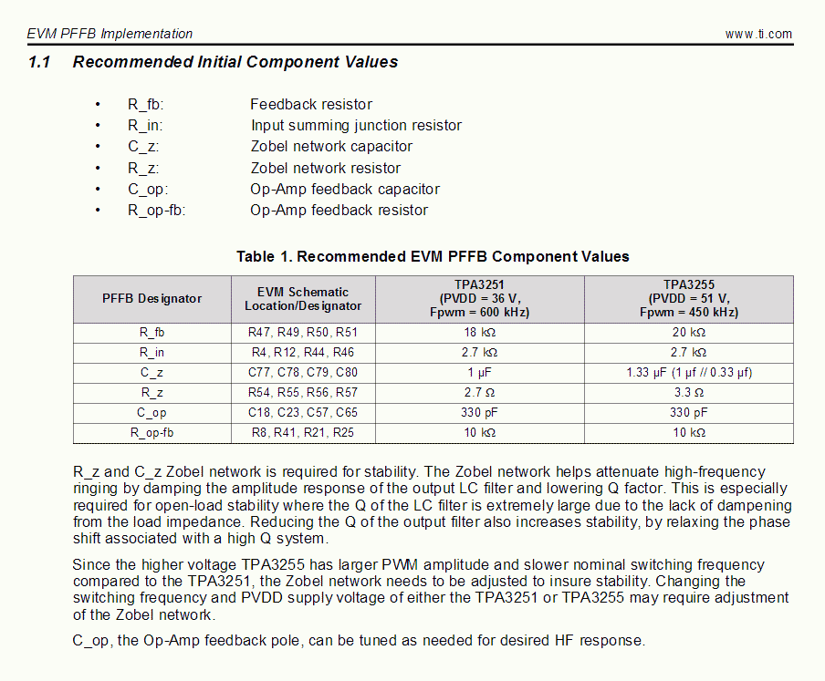
http://www.diyaudio.com/forums/attachment.php?attachmentid=692214&stc=1&d=1531763562
Sorry to dig back so far into the past… could you please elaborate on “the newer implementation” for PFFB on the EVM? Is it what is described in the slaa702 TI notes, or is it something else that the community has developed that is overall superior?The influence of PFFB on the EVM is less than 6dB, which can be seen from the latest documents at TI. With a good design, which the EVM is, there's (to me) no need for PFFB. With cheap inductors and "bad layout" the performance boost is much more present.
Hmm... I suspect you were referring to the implementation in SLAA788A (rev March 2018) vs SLAA702 (July 2016).
Hello,TPA3255EVM
Hello,
Bypassing op-amps on my TPA3255EVM was a succes
Installed final wiring and put cover back on
Difficult to put in words
I like what i am hearing 🙂
I can easily say the best free tweak i ever did 😀
Enjoy...
this is my first post and I need some help.
I am total noob in this so I am very cautious not to burn my TPA3255EVM Board.
I would like to try the setup you posted. Connecting XLR connector to the J28 interface.
My question is, how did you turn off opamps and is it necesary?
If I understand right you just need to short all 4 RCA connectors + connected to - or am I wrong?
can you use 3 pin J10 and J12 instead?
Thank you for your answer.
@ iske, have a look there 😉
You could connect the balanced inputs to the audio interface board, pins 11, 13, 15, and 17. Connect ground to pin 21. I think a 20 awg solid wire can easily be pushed into each pin.
This would bypass the op amps, and leave only the 10uf coupling capacitor in the signal path.
The chip's input impedance is 20k.
Mike
- Home
- Amplifiers
- Class D
- TI TPA3255EVM