Thanks Andersonix,The first picture I found of an SL-10 has caps showing their polarity:
And there we have it. The Threshold strip on the wrap indicates the positive side just like the Instrument Device caps in the SL10. I did notice one Instrument Device cap that was installed incorrectly, soo, maybe the red or black dot on the bottom is still a possibility. When I do this, I'll make sure to test several caps (including the one suspected of incorrect installation) and report back.
as is must take apart the pcb , test non powered pin to ground is best to do ,or just look...😉The absolute sure-fire way would be to power it up and measure the voltage on the cap pins.
You may get advise here that might or might not be accurate ;-)
Jan
I promise, I will do both!
It's just nice to have a few confirmed ways of identifying.
For all you "Test it" folks out there, remember, I did find one that was installed backwards. I confirmed that by looking at a second SL-10 I had and the picture posted. All the testing in the world would not have told me it was backwards.
It's just nice to have a few confirmed ways of identifying.
For all you "Test it" folks out there, remember, I did find one that was installed backwards. I confirmed that by looking at a second SL-10 I had and the picture posted. All the testing in the world would not have told me it was backwards.
^ Actually, it would have. You would have seen a more positive voltage on one side. The caps with the positive marked (instead of negative) would have been an issue, but I presume the replacement caps will be the common negative stripe variety.
You're saying had I tested the incorrectly installed cap, I would have noticed positive voltage in one position and negative as I switched the leads around.
If I were to test all the caps, I would have noted that the one, incorrectly installed cap, had makings opposite to the rest and deducted it was installed backwards?
If I were to test all the caps, I would have noted that the one, incorrectly installed cap, had makings opposite to the rest and deducted it was installed backwards?

On some circuit boards the positive pad is square, no? Don't remember exactly, but the pads aren't always the same. The magic marker idea is a good idea no matter what. And just to say it, not all caps necessarily face the same direction. No rule there.
Am I doing this right?
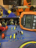
Cap in question seemed to be installed "backwards". I have a woking SL-10 and we have the picture above to compare. I decided to test the polarity on the board of the known working SL-10 and the pictures shows what I got.
The tantalum capacitor is clearly labeled. I tested both the top and bottom of the board as it has traces on both sides (I don't think any layers). I tested with the cap in and out.
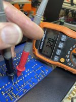
I did switch the cap in that location on the other SL-10 and put it on a variac. It works fine, I tested everything.
Am I not measuring Correctly? (Yes, leads are installed correctly on the DVM)
Cap in question seemed to be installed "backwards". I have a woking SL-10 and we have the picture above to compare. I decided to test the polarity on the board of the known working SL-10 and the pictures shows what I got.
The tantalum capacitor is clearly labeled. I tested both the top and bottom of the board as it has traces on both sides (I don't think any layers). I tested with the cap in and out.
I did switch the cap in that location on the other SL-10 and put it on a variac. It works fine, I tested everything.
Am I not measuring Correctly? (Yes, leads are installed correctly on the DVM)
Attachments
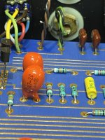
Something that bothers me anytime that I see them are 'empty holes' where component leads go. Then they are soley reliant on the through hole connection on the board to be perfect. Especially when a component is removed and then put back in place, it creates a place for Murpheys law to get a foot in the door. You won't see it because it is where you can't. I am seeing several of these on your board, even the resistor right next to the cap in question.
- Home
- Amplifiers
- Pass Labs
- Threshold SL-10 Recap.What's the Polarity of the 470 uF Black Threshold Caps??