Hi all.
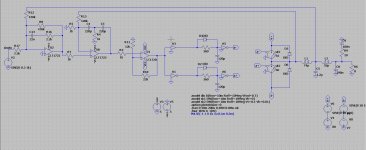
I had idea when corona is in afterworld to go try multilevel, the problem however is the driving of gates who are floating.
I have read some stuff, but simulating it is very difficult, I did see that I even have to use high side driver ic,s and not the LMG1505 whi I try now.
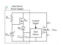
Problem is I use symetrical supply, -60 x +60 volts. Normally I have to put then VSS on the -60 and level shift the inputs. But in flying cap three level I have als supply / 2 levels, and I think I need here isolated drivers.
Do have someone some experience? and why the vdd 5 volts does not work when tied to the -60 volts rail.
I have then use a btl? who by the way give then 5 level when I do shift triangle 90 degree. Maybe the lmg1505 does not work with symetrical supplys.
https://core.ac.uk/download/pdf/158315636.pdf
Here some examples what I mean. This idea for openloop Gan, just curiousity of me, I see nice things happen, amps who are better then class A for example, need to hobby test afcourse in future.
regards
I had idea when corona is in afterworld to go try multilevel, the problem however is the driving of gates who are floating.
I have read some stuff, but simulating it is very difficult, I did see that I even have to use high side driver ic,s and not the LMG1505 whi I try now.
Problem is I use symetrical supply, -60 x +60 volts. Normally I have to put then VSS on the -60 and level shift the inputs. But in flying cap three level I have als supply / 2 levels, and I think I need here isolated drivers.
Do have someone some experience? and why the vdd 5 volts does not work when tied to the -60 volts rail.
I have then use a btl? who by the way give then 5 level when I do shift triangle 90 degree. Maybe the lmg1505 does not work with symetrical supplys.
https://core.ac.uk/download/pdf/158315636.pdf
Here some examples what I mean. This idea for openloop Gan, just curiousity of me, I see nice things happen, amps who are better then class A for example, need to hobby test afcourse in future.
regards
Attachments
Last edited:
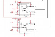
I was so close, but with some help of mine TI friends I know now how, it was more simple as I thought, just use it as pic two with the yellow gate driave and two halves of that gate drive..
Hi Kees52, you just share a good topic here. With Gan and multi-level design, how many watts do you need for this amp🙂? It must be a giant monster here.I personally think this topology is good for the chip design. If i'm right, Infenion has this similar chip amplifier.
And, i think class D amplifier with multi-phase interleave topology maybe a good design trend for high-end amp.
And, i think class D amplifier with multi-phase interleave topology maybe a good design trend for high-end amp.
Hi Erica.C
I have not the attention to make a giant monster, but it is possible yes because the stress for each fet is dramatic lower and it has frequency multiplication who is the interesting part, making the bandwith of the amp dramatically higher and high quality audio is for shure possible, the pic with 6 level and signal harmonic pic in it has small feedback and the carrier is shifted to 3 Mhz, also mosfets can be much smaller and as result the Nc is much lower making smaller deadtime.
I have simulated one in past, harmonic distortion -100dB did that.
But she need more parts and also more difficult to make.
I now the small chip with 5 level, that are two three level with 90 degree difference.
regards
Attachments
Last edited:
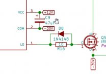
The friends from Gan and IT has give me this idea, never now that I has to use a half gatedriver, th High side because it has a level shifter in it making things easy.
but I get overlap of signals who need to be above and below om 40 volts, half of 80 volts for proper three level, maybe LTspice has difficulties with this kind of simulations.
but I get overlap of signals who need to be above and below om 40 volts, half of 80 volts for proper three level, maybe LTspice has difficulties with this kind of simulations.
Attachments
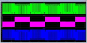
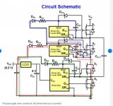
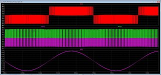
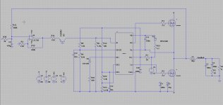
Wel at last I have work myself through the stuff for flyning cap, the bad pic where the three level swichting was not so nice and faulthy was because of capacitor balancing, just two 150 K resistors did change things for the good, balancing. last pic you see three level bas version, no or bad doubling if carrier.
Attachments

I have look some in older designs I did simulate.
This one did also quite good, it has a very low distortion, and pre andpost feedback.
It is free to make for the people who want if she share real results..
regards
This one did also quite good, it has a very low distortion, and pre andpost feedback.
It is free to make for the people who want if she share real results..
regards
Attachments
I have a circuit for feedback for class D who uses forward error control, it does quite fine and is a resistor network, so no integrator used.
I get quiet a good phase from input to output with almost no shift on 30 kHz, so the error correction for correcting the phaseshift for the low pass filter does nicely, it is for post feedback., I did have this from a paper I get from Charles lehmann to study it, for a flying cap tree level it does work. I have seen more papers of it but still post-feedback is a big problem because of phase shifts who does make amp unstable, and feedback does get less good on high frequency,s I have here test it on the edge of 30 kHz but also 100 kHz (max bandwidth) did give HD as low as -70dB with 1.2 MHz switching (doubled carrier three level).
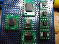
Some test boards, need for using the smd parts, I did put them on adapter PCB so I can build and test.
I need some good solder for the smd, I have some from China but it is so dry and hard I can not use it, if somebody now a good supplyer for that liquid solder stuff I like to now. I have now solder the parts with normal solder.
regards
I get quiet a good phase from input to output with almost no shift on 30 kHz, so the error correction for correcting the phaseshift for the low pass filter does nicely, it is for post feedback., I did have this from a paper I get from Charles lehmann to study it, for a flying cap tree level it does work. I have seen more papers of it but still post-feedback is a big problem because of phase shifts who does make amp unstable, and feedback does get less good on high frequency,s I have here test it on the edge of 30 kHz but also 100 kHz (max bandwidth) did give HD as low as -70dB with 1.2 MHz switching (doubled carrier three level).
Some test boards, need for using the smd parts, I did put them on adapter PCB so I can build and test.
I need some good solder for the smd, I have some from China but it is so dry and hard I can not use it, if somebody now a good supplyer for that liquid solder stuff I like to now. I have now solder the parts with normal solder.
regards
Attachments
Last edited:
Good work. I would recommend just getting PCBs made for SMD work as the cost is so low for a basic 2 layer board and performance will be improved.
Multilevel to me looks useful for higher power amps (EMI, Efficiancy, filter size) and IC amps (lower cost of more FETs, smaller passives). It would be interesting to see a 'best effort' 2 level design compared with a multi level design for efficiency and output spectrum.
Multilevel to me looks useful for higher power amps (EMI, Efficiancy, filter size) and IC amps (lower cost of more FETs, smaller passives). It would be interesting to see a 'best effort' 2 level design compared with a multi level design for efficiency and output spectrum.
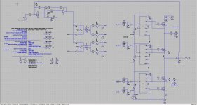
Hi
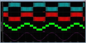
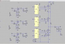
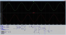
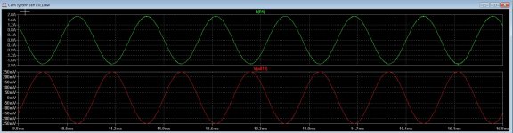
The schematic you see is a flying cap, and do three level output.
when in bridge and audio input out of phase you get 5 level. The reason also to do this is distortion is already much lower as with a normal version class d and mosfet does work on low carrier because of doubling, and with 5 level
tripling of carrier frequency.
The pcb is for test, I can use smd here, just with care I can easely do tests.
regards
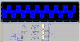
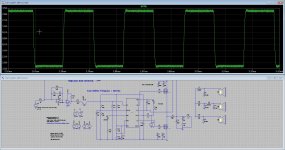
Oke, I have the idea of a old way, I make a self oscillating system with a comparator who has a window, now the oscillating is very stable, and one resistor does set the frequention in a easy way.
Now I go calculate feedback, try also current feedback, nested feedback etc.
R3 = 3.3k give 400Khz carrier who is very stable.
Now I go calculate feedback, try also current feedback, nested feedback etc.
R3 = 3.3k give 400Khz carrier who is very stable.
Attachments
Last edited:
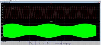
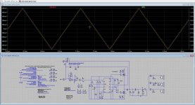
I have now a front end for further work, this frontend uses a lead corrector and include the low pass. As you see the supply ripple is perfect corrected,
output (20Khz) in fase with input..
now I can go work on the cascaded extra stages for more open loop.
It is already now very low distortion.
regards
output (20Khz) in fase with input..
now I can go work on the cascaded extra stages for more open loop.
It is already now very low distortion.
regards
Attachments
Last edited:
I have to say the importances of a speaker model for simulating feedback systems, See the pic,s, one with resistor and one with speaker (has 1.2 Kilovolts over it because of filter resonance into feedback.
The models contain a woofer, tweeter and mid, so you can make a complete three way speaker model and use it for optimizing.
regards
The models contain a woofer, tweeter and mid, so you can make a complete three way speaker model and use it for optimizing.
regards
Attachments
I have play with some idea,s for feedback, as I did see there is need for quite high open loop and strong (corrected) feedback
I ask myself does these sound well.
I have here circuit made with simulating feedback and placing poles and zeros al over the place.
I need however an idea to simulate feedback with ltspice the good way,, I can not do a AC analyses with the switching part but
need some gain block for that.
Idea, let me now.
Here I have included some sims, with speaker models (three way) and open output, looks like this does well, the square 10 kHz is
a good way to adjust poles and zero,s for low pass correction, it does the open output peak very well, and this is needed tot not
blow the amp.
See also the triangle, I did input, and see how close it is on the output *pre-post feedback.
Busy with soldering now.
Attachments
Hi
This is a self oscillating version. I have simulate it with open output, a three way speaker model, and a resistor, it stays stable. It needs to correct in a fashing way to keep it oscillating and stable. What you see is a preamp it needs still a cascaded extra feedback path to get distortion some lower., Yes a smps does the same, it is very important to put polers and zero,s on the right place. PID contriol is more used here then class D. I ask myself or extensive feedback does make it sound right, special when gain of lower distortions is just a 0.05 to 0.001.
I have a question, I do simulate feedback and put lead and lag there, but for AC analyses I can not use a normal schematic, I need a non lineair gain block, can you help me here? How I do that make a compleet feedback block in LTspice for AC analyses.
thanks.
I have a question, I do simulate feedback and put lead and lag there, but for AC analyses I can not use a normal schematic, I need a non lineair gain block, can you help me here? How I do that make a compleet feedback block in LTspice for AC analyses.
You don't. You use your complete switching model and the method suggested by Mike Engelhardt in the link provided. Break the loop at the output of your error amplifier and insert the [sine 0 100m {freq}] source. Label the node on the amplifier side as A and the other side as B and perform the analysis as something like,
.measure Aavg avg V(a)
.measure Bavg avg V(b)
.measure Are avg (V(a)-Aavg)*cos(360*time*Freq)
.measure Aim avg -(V(a)-Aavg)*sin(360*time*Freq)
.measure Bre avg (V(b)-Bavg)*cos(360*time*Freq)
.measure Bim avg -(V(b)-Bavg)*sin(360*time*Freq)
.measure GainMag param 20*log10(hypot(Are,Aim) / hypot(Bre,Bim))
.measure GainPhi param mod(atan2(Aim, Are) - atan2(Bim, Bre)+180,360)-180
.param t0=1m
.tran 0 {t0+25/freq} {t0} 10n uic
.step dec param freq 10K 1000K 20
.save V(a) V(b) V(out)
.option plotwinsize=0 numdgt=15
When it is complete view the spice error log, right click and plot stepped data then add trace gain to the plot.
Follow the instructions.
https://www.analog.com/en/technical...imulation-and-why-you-usually-don-t-need.html
Hi There
I go try, ver much thanks for the help, and wish you a happy new year (forgotten to say)
I was some months back busy with multilevel flying cap, the feedback for it did not as well as the normal versions because of canceling
carrier fundamental and fase shifts, get a ripple on peak sinusoidal 1 Khz test and clean signal when crossing zero because of this, but I
did see that this was not such a problem, I am now already learning class d for 4 months, it is quite complicated calculations, a good
software for feedback loops are nice like in pdf included..
Mike Engelhardt sounds dutch by the way.
Update
Did test that, but it uses uge time to get through all these measurtements. Then I mean really uge.
Attachments
Last edited:
No worries. When you do it copy and paste the previously given statement into a single directive box.
The analysis might take some time. This statement does 61 separate analysis to get the final result. You do need to have a nominally stable loop in the first place for things to work and you might get the occasional dropout.
The analysis might take some time. This statement does 61 separate analysis to get the final result. You do need to have a nominally stable loop in the first place for things to work and you might get the occasional dropout.
Attachments
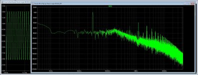
Hi There
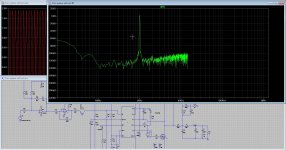
I have did this now and it is simulating, but busy already with the first plot. stil busy with 1/41 so this takes hours.
Maybe models are cause, I do use normal models, but can switch to simple models.
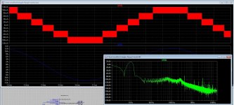
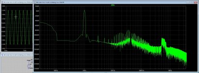
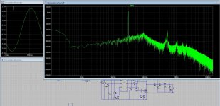
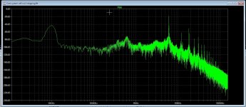
I have a plot of the first run 1/41. See 6 Mhz signal peak, who is very high so maybe it does oscillate there, normally it does on 400 khz in normal simulation.
I have did this now and it is simulating, but busy already with the first plot. stil busy with 1/41 so this takes hours.
Maybe models are cause, I do use normal models, but can switch to simple models.
I have a plot of the first run 1/41. See 6 Mhz signal peak, who is very high so maybe it does oscillate there, normally it does on 400 khz in normal simulation.
Attachments
Last edited:
- Home
- Amplifiers
- Class D
- Three level flying cap Gan.