Yup. Sorry 10K to 1000K at 20 points per decade would be 41 steps. It does speed up as the numbers rise but you might try setting the minimum step size to a higher value,
.tran 0 {t0+25/freq} {t0} 10n uic -> .tran 0 {t0+25/freq} {t0} 100n uic
note that the t0 + 25/freq gives the number of cycles [25] each analysis runs for so 10KHz will take 1mS + 25*0.1mS times how fast your computer is and that time will go down as the analysis progresses.
Also try looking at V(out) whilst its running. The perturbation is only 100mV and the loop will act to try to keep the output at zero. For a self oscillating design that will mean that the circuit is operating at its highest frequency.
If you want to see the behaviour at higher outputs you will probably have to trick things by applying a DC input to the error amplifier to bias the output closer to the power rails.
Oh, and as you suggest simpler models may help but why not go cook a meal?
That will be a big meal then, But I watch tv now, russia/nato looks not good.
I will try that what you say, I can also use triangle version and use then this feedback, I think that will work also.
I will try that what you say, I can also use triangle version and use then this feedback, I think that will work also.
The idea is that the 100mV disturbs the loop but does not overdrive it. Again the loop will try to keep the output at zero so if you want to see the low frequency switching and gain in a self oscillating amplifier you will have to drive its output up with another DC source at the input to the error amplifier. It looks like your loop has gone unstable in the case of the red plot. You should really just be plotting the direct traces for a and b and possibly the output whilst the analysis is running in order to see how things are going. It may also be worth checking the nature of the waveforms at the point you use for injection. Ideally you want it to be as quiet as possible. Perhaps you can post a model for me to poke about with?
Hi There
Oke I do give you the schematic to try, because I do maybe things wrong.
I feel I miss something in it.
You now how to use models I presume.
thanks.
Oke I do give you the schematic to try, because I do maybe things wrong.
I feel I miss something in it.
You now how to use models I presume.
thanks.
Attachments
Last edited:
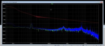
I did get now this when do longer sim.
For clearity, the purple line above 0 dB is because I did let it not run out, this line I get when I
am able to see the plot, all below are compleet runned, that is why you see it like this.
We have need for better sims and class D design tools. because of in time errors of these amplifiers.
For clearity, the purple line above 0 dB is because I did let it not run out, this line I get when I
am able to see the plot, all below are compleet runned, that is why you see it like this.
We have need for better sims and class D design tools. because of in time errors of these amplifiers.
Attachments
OK, understood about the incomplete run. I'll have a look at your models tomorrow but all I might have is a faster processor. Time for bed!
Hi Sleep well.
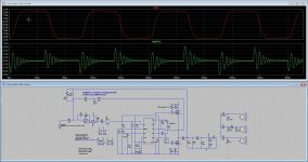
I have done some reading, I can simplify the frequency's of interest, I have put in a extra measurement point to see switching, that works, but sill I also see a carrier at 7 Mhz who cause the slowdown of simulation badly.
I have a intel I3 3,2 G speed. need some day a i7 or better for such complicated sims.
Update,
The 7 Mhz carrier looks like a second oscillation on a very high frequency, this can happen when feedback is somewhere cause a second fase where this happens, so somewhere higher it rises again above unity and hits a oscillation point. caused by the zero/pole integrator, I did put a zero into postfeedback to correct, put osc frequency also some lower, now i have speed I can say.. Also do restrict frequencions measured to two full cycles only, who seems to be enough, (I think).
This sim is quite usefull. I did see things I did not see first.
Attachments
Last edited:
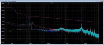
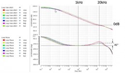
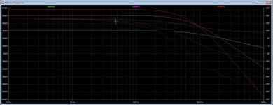
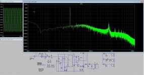
I have simplify the frequency's to test, now from 100 Hz to 30Khz.
here is the result I did see, after correct schematic to get no 7 Mhz oscillation happened, only the fundamental.
I see that gain is 62 dB and phase stays in save area if I read well, but fase is close to 180 degree, so need some more correction on lead circuit.
here is the result I did see, after correct schematic to get no 7 Mhz oscillation happened, only the fundamental.
I see that gain is 62 dB and phase stays in save area if I read well, but fase is close to 180 degree, so need some more correction on lead circuit.
Attachments
Sorry to disappoint but unfortunately I don't think I can help you out here. I have tried to implement your circuit, there were a couple of models buried somewhere else on you hard drive that I had to scrape from elsewhere and then bodge into my own version. Mr Analog is way above my pay grade but I don't think the behavioural model he provides fully/properly implements the features of the driver. Specifically over current protection and programmable dead time. It looks like the drive characteristics will/should match the IC but as a result I think you may have spent/wasted some time trying to find a particular mosfet and its associated spice model that gives you good, for various definitions of 'this one works', results.
Beyond that, and I know nothing, having looked at what might be going on self oscillation appears to have its fundamentals somewhere beyond or perhaps in the middle of what Mr Putzeys has disclosed and without understanding the parts he has missed out you cannot reasonably arrive at a viable and robust solution. IIRC he has suggested as much in reference to his patents and leaving out the 'secret sauce'. This leaves you placing arbitrary poles and zeroes in the loop whilst mixing feedback points and hysteresis in with them until your model appears to self oscillate until you find out that it does not or does at some weird frequency. Then you build one in real life and it is a disappointment.
Again. Apologies for the fail.
Hi
You don not have to be feel you disappointing me, it was a very nice learning process to get more out of LTspice. I am very thankfully you did help.
For the feedback the lead/lag corrective stuff, I need just to calculate that, and simulate, I do not think I can use this LT spice model for that, but it is very useful
to let it do what will be result of open loop between the audio band.
As you say, real live build will do, so I go make one as a front end so I can experiment, the dead times by the way was included into the model of gate driver ic UC 28** Calculating the self osc frequency is easy, this is not the problem, never was, it is included into the loop, I did use the simulation to see what it does, while knowing that this model was for a supply and not class D, but it does for a part the same because it is a buck version, the different is buck does work on resonance of low pass to get voltage, and D does stay way below to use it as a demodulation with suppression of carrier.
This was the last sim, I did remove some frequency's to speed it up. Nice to see that open loop is 64dB and fase stays within save area but it does not give part values, still I need to calculate myself. As I already did now, a good feedback calculator will be a nice solution, it does exist, like Ice power has that for get good results. But that class d amp just uses a PID for lead/lag control low pass filter.
All the designs except digital (future??) will do the same, all the patents does not have that much differences
regards
Attachments
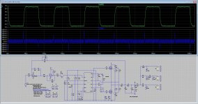
I have done other ways for open loop, that does better en faster.
I have the most easy and best way to set the feedback lead/lag correction by using a 10 Khz square, if these is looking nice
distortion is also low as I did see. I did this also with normal amp as the circlotron, washing away the overshoot did make it sound
better.
Because this is a self oscillation system we need stability when open output or connection of speaker system with complex impedance.
If not it stops oscillation and blow, or it drops to low frequency making it a buck converter with 500 volt output or so, bye bye speaker.s
protections are as such mandatory. But that we now alreay. See the pic,s
Attachments
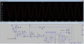
Here some idea what happen with use of square,s if these looks good, we have enough open loop gain.
If to much gain and extensive low distortions, I do not now it sounds well, somewhere we need to put a
stop with that, feedback needs as low as possible.
If to much gain and extensive low distortions, I do not now it sounds well, somewhere we need to put a
stop with that, feedback needs as low as possible.
Attachments
You're still driving it wrong. Go back and carefully read how Mike tells you how to do the analysis. Another version of the words is here,
https://www.analog.com/en/technical...-steps-in-generating-a-bode-plot-of-smps.html
You have to run the analysis to completion and collect as many points of data as you can. That means you have to be patient, not make up your own version and then look at the wrong thing.
Once the analysis is complete right click on the plot, select view, select view spice error log. Then in that text window right click, select plot stepped data and say yes to complex data. You will get another plot window. Click add traces, click gain. The bode plot of loop gain will be plotted.
Don't blabber on about the method as given only applying to buck convertors because buck convertors are used in the examples. It is generally applicable to any switching supply including a Class D amplifier.
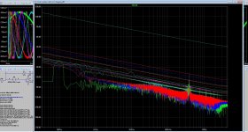
I did change some to look at what happens.
I have here also a open loop plot of a cascaded feedback branche. This go very fast.
but it has no complete feedback to see how stable it is.
On pic this is a cascaded feedback, I can see the open loop easely here above 50dB
I will look again on the simulations, I will make a model who is fast changing output. I have read
that the dc cource need a high impedance input and I have this on the opamp, I has first did
set it different, as I read and later I did switch.
Do you now I have also pre-post feedback who has two feedback feeds? Then I need to put voltage source
between output and the feedback network. I did never did by the way, I go try.
Better is put that in the schematic what you means, then I can tell. PS what pc I need for fast sims? I
go upgrade it. I seems to have a intel I3.
Attachments
Last edited:
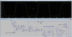
This outcomes I did not with that simulation model but with calculation and
square testing. I have stable system, even with open output and connected three way
speaker system in sim. The error correction response does well on pic 1, fast rise times as you
see triangle form error signal. Pic 2 I have
slow down the error correction response on the low pass filter getting slower rise times so you see
more sinusoidal error signal. Testing is on 10 Khz.
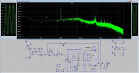
Pic 3 is sim distortions, on 10 Khz it gets to -100dB it can even better, but then stability
gets bad.
Compromises are really an important part of these designs, more, much more then with analog
circuits.
square testing. I have stable system, even with open output and connected three way
speaker system in sim. The error correction response does well on pic 1, fast rise times as you
see triangle form error signal. Pic 2 I have
slow down the error correction response on the low pass filter getting slower rise times so you see
more sinusoidal error signal. Testing is on 10 Khz.
Pic 3 is sim distortions, on 10 Khz it gets to -100dB it can even better, but then stability
gets bad.
Compromises are really an important part of these designs, more, much more then with analog
circuits.
Attachments
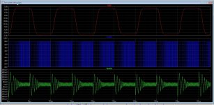
Here I have a version with only prepost feedback, have it very stable, even with open
output or connected inductive/capacitive load the square keeps very nice.
Now I can set the voltage source and a and b on the right spot to see what happens.
But do tomorrow, I go walk to the cold and fog and then sleep.
regards
output or connected inductive/capacitive load the square keeps very nice.
Now I can set the voltage source and a and b on the right spot to see what happens.
But do tomorrow, I go walk to the cold and fog and then sleep.
regards
Attachments
Hi
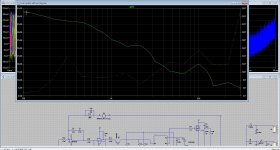
I have don this, now I can see that the gain go like it needs to do.
Start with 54dB and go to zero at unity.
Did use less frequency's as a fast test, I do restore original and do all tomorrow to see.
But as I thought, with a square test I can optimize also, I did proof, because it was stable
and low hd. But it is usefull I think.
thanks.
Attachments
I see you finally got there so the following is probably superfluous.

It's self oscillating based purely on a delay in the buffer, A1.
I've lifted out A and B as separate behavioural sources which let you change VIN and VAC as appropriate to plot loop (VEA/DIN) and closed loop (OUT/VIN) gains.
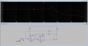
This is the first run, of 41, for loop gain.

Note that V(a) has the perturbation imprinted on it. The loop acts to reduce this, at V(b), to zero.
After the analysis is completed.

You can see V(b) rising as the loop runs out of steam at higher frequencies.
Right Click. View, Spice Error Log, Right Click, Plot Stepped Data and say yes to complex. Right Click, Add Traces, Choose Gain.

The Loop Gain. Basically a first order 20dB/Decade roll off with 90 degrees phase shift due to CINT around the error amplifier.
As you suggest you have to suck it and see then make some choices as to how the analysis should be run. Particularly the minimum step time and number of points per decade and also how large you make the disturbance. Also where you locate the disturbing source. If you make things too relaxed then you will end up with noisy plots and this is likely to happen anyway by virtue of the nature of the systems you are analysing.
Again I am not really qualified to comment but if you produce an exclusively linear model of your loop and perform the analysis in the same way you will get a bode plot but the amplitudes will be scaled incorrectly because you have not included the modulator gain in the system. That arises from the comparison of the low frequency audio signal to the, attenuated, ripple signal at the switching frequency at the input to your comparator.
It's self oscillating based purely on a delay in the buffer, A1.
I've lifted out A and B as separate behavioural sources which let you change VIN and VAC as appropriate to plot loop (VEA/DIN) and closed loop (OUT/VIN) gains.
This is the first run, of 41, for loop gain.
Note that V(a) has the perturbation imprinted on it. The loop acts to reduce this, at V(b), to zero.
After the analysis is completed.
You can see V(b) rising as the loop runs out of steam at higher frequencies.
Right Click. View, Spice Error Log, Right Click, Plot Stepped Data and say yes to complex. Right Click, Add Traces, Choose Gain.
The Loop Gain. Basically a first order 20dB/Decade roll off with 90 degrees phase shift due to CINT around the error amplifier.
As you suggest you have to suck it and see then make some choices as to how the analysis should be run. Particularly the minimum step time and number of points per decade and also how large you make the disturbance. Also where you locate the disturbing source. If you make things too relaxed then you will end up with noisy plots and this is likely to happen anyway by virtue of the nature of the systems you are analysing.
Again I am not really qualified to comment but if you produce an exclusively linear model of your loop and perform the analysis in the same way you will get a bode plot but the amplitudes will be scaled incorrectly because you have not included the modulator gain in the system. That arises from the comparison of the low frequency audio signal to the, attenuated, ripple signal at the switching frequency at the input to your comparator.
Attachments
Last edited:
We have in class D some more needed to get the bandwidth right, so the feedback system is more complicated.
You mean I have to include the modulator gain also by putting the voltage source between comparator and error
amplifier?
I do see you have for sure much more experience with LTspice, here I am not that good with because it is quite
complicated mathematics formula's and I am really bad with calculations, I was also on school. But we have
calculators and pc,s these days ease some things..
I go include fast models in schematic and do some more tests, that way it sims a lot faster.
Thanks for your help.
PS I did read the way this need to be done, I did saw I can freely change the frequency's needed, I mean
can even use just one to see gain on that. But see now also when I need much more clearance I need
to include enough data.
regards
- Home
- Amplifiers
- Class D
- Three level flying cap Gan.