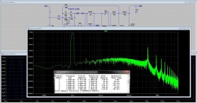
And this is a cascaded 5th order, gain (60dB) stays constant in audio band. with proper forward resistors and tuned it is even more gain
but no post feedback. Icepower by the way uses this nested feedback loops with lead corrector.
it looks like this, and oscillate slightly above 700 Khz.
I did stop with it because of 5 opamps needed.
have a nice day and sleep well.
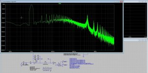
but no post feedback. Icepower by the way uses this nested feedback loops with lead corrector.
it looks like this, and oscillate slightly above 700 Khz.
I did stop with it because of 5 opamps needed.
have a nice day and sleep well.
Attachments
I was busy working and saw this coming by.
https://github.com/YetAnotherElectronicsChannel/ClassD_Amplifier
Here AC simulation is used for feedback gain in a linear model.
And I have did look wrong on model you gave, I have mix things. I have to look at phase
crossing 0dB only? it's crossing with signal itself is not of importance to get oscillation freq.
Maybe download is interesting for learning more. I did see that I am not the only one who get
it not that into mine head, class d is complicated..
But for now, I get slowly into the right pad, model you did provide is quite as interesing as AC who last
one can not do switching part, you have in one circuit use a lineair model also for ac.
Thanks for help me.
Last edited:
Hi There
Mine first question about crossing signals is clear.
I have test it to satisfy myself, the beauty of simulation.
So now I can go on with the important things.
Get as much open loop in audio bandwidth as I can, but also keep the signal after 0dB unity point as deep as possible
you did -30dB with playing on poles and zero,s I need to read also some more
and satisfy the stability. these three are quite connected, so we need to make compromises.
I did see and try some more topologies, I am not alone in the complicated way class d has to be designed.
Yes Gan will easy things a lot in future.
regards
Attachments
Have get it now about crossing signals, the fase needs to be in place
with lag compensator like you did before modulator but still spice is not
for me because it is to complicated and I am quite numbers blind so to say.
I go see to lag the phase into place where suppression of ripple is max.
Your idea to start with triangle to make it more easy I consider. The zero crossing
(unity) I do get now, your high pass lag Rpole Cpole is a help to get there.
But now, as you see I can reach very low distortion, butttt ripple get,s worse, here
is the difficulty. your previous example did well with ripple -35dB but distortion
was much higher.
Oké, such low distortion with just one op amp, is quite good but you have no dead time
so it's outcome will be false in some extent, it is not real but sim.
regards
Attachments

Last edited:
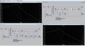
Here I am again, I work so hard.
Oké I have use your liniar model to get the compensator right and see how it does.
You did say (I had not read)
I can tell you it is quite accurate, and very usefull to look at the plot of the opamp corrector.
I have done some compare with your and mine setup around the op amp, I did see not much different.
The fase lag did set correct the carrier frequency, nice done, model is helpful thanks.
Also I did the open loop without feedback from output, a simple one, I can see the signals do like in a PID controller
correcting for unstability icepower does also use it as a lead/lag compensator. In fact we do also.
When use then the parts set in the open loop setup, then things do not match. So yours is the best.
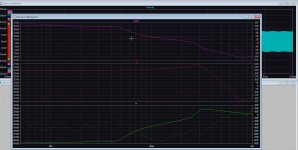
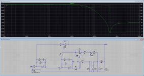
pic 1 is with the low pass filter, the corrector's zero needs to be set on cutoff low pass, yours do peak a little so Q =1
did read somewhere that these are easy'r to include and compensated. I did even think on 4th order Bessel, but
so much people have done that, I have read a lot of papers.
regards
Oké I have use your liniar model to get the compensator right and see how it does.
You did say (I had not read)
Here the gate, Modulator, has been replaced by a Voltage Controlled Voltage source with a gain set to the nominal Vhigh=2.5 Vlow=-2.5 of the gate including a delay element in the cunning expectation, hope, of getting a 'correct' result for loop gain in the linear representation.
I can tell you it is quite accurate, and very usefull to look at the plot of the opamp corrector.
I have done some compare with your and mine setup around the op amp, I did see not much different.
The fase lag did set correct the carrier frequency, nice done, model is helpful thanks.
Also I did the open loop without feedback from output, a simple one, I can see the signals do like in a PID controller
correcting for unstability icepower does also use it as a lead/lag compensator. In fact we do also.
When use then the parts set in the open loop setup, then things do not match. So yours is the best.
pic 1 is with the low pass filter, the corrector's zero needs to be set on cutoff low pass, yours do peak a little so Q =1
did read somewhere that these are easy'r to include and compensated. I did even think on 4th order Bessel, but
so much people have done that, I have read a lot of papers.
regards
Attachments


Last edited:
Hi There
Have read this thread again to look at the distributions, I did miss some as I did not take enough attention.
Oke I do understand now what to do, and to get clean signals, but most is by the output low pass, I have use a Bessel
4th order for suppress the carrier, and it works better with the feedback, butter worth does also giving even more with
a 4th order for example ice power does use them. and it is easy to implement on one core.
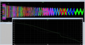
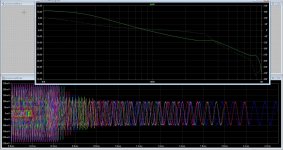
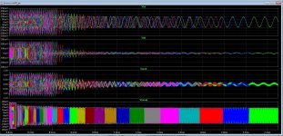
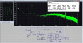
here are the plots, use 1 mv input. and the resulting distortion on your choice model who is course perfect and miss dead time and such.
Need to test this with mine schematics after find the best way.
Now I can have some fun, forget the other troubles.
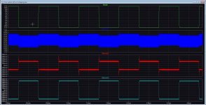
first pic is 12 dB original filter, the two others are 24dB. one 100 mv, and one 1 mv input. the last is the normal test.
regards
Have read this thread again to look at the distributions, I did miss some as I did not take enough attention.
Oke I do understand now what to do, and to get clean signals, but most is by the output low pass, I have use a Bessel
4th order for suppress the carrier, and it works better with the feedback, butter worth does also giving even more with
a 4th order for example ice power does use them. and it is easy to implement on one core.
here are the plots, use 1 mv input. and the resulting distortion on your choice model who is course perfect and miss dead time and such.
Need to test this with mine schematics after find the best way.
Now I can have some fun, forget the other troubles.
first pic is 12 dB original filter, the two others are 24dB. one 100 mv, and one 1 mv input. the last is the normal test.
regards
Attachments

Hi There
I am here again, I have play with your model if you don't mind so I get some more easy with LTspice, but
it stays complicated.
Have set some more stuff in the circuit and did use a extra feedback from switching output to get the carrier, however now it is
not on 0dB anymore, extra phase is in that low pass if is a phase shift oscillator.
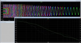
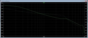
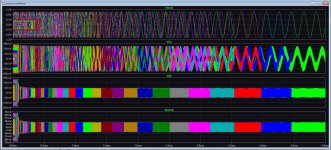
Maybe this way I can sim better and change things to see what happens. did put two plots, with just some changes I did set a PID
error amp in circuit to play with. see on pic how it changes, But I have better idea's than a PID who does not well on higher frequency's
in audio band. You see clear that out of band noise is a lot lower now on output of error amp and does show the direction I need to go.
Go play with some more, a shortcoming of pre-feedback is aliases error who make HD bigger but is is also stable and it is not together
with audio, have different path for both, helps with noise, as you did mention by the way🙂
Interesting stuff.
have a nice weekend.
I am here again, I have play with your model if you don't mind so I get some more easy with LTspice, but
it stays complicated.
Have set some more stuff in the circuit and did use a extra feedback from switching output to get the carrier, however now it is
not on 0dB anymore, extra phase is in that low pass if is a phase shift oscillator.
Maybe this way I can sim better and change things to see what happens. did put two plots, with just some changes I did set a PID
error amp in circuit to play with. see on pic how it changes, But I have better idea's than a PID who does not well on higher frequency's
in audio band. You see clear that out of band noise is a lot lower now on output of error amp and does show the direction I need to go.
Go play with some more, a shortcoming of pre-feedback is aliases error who make HD bigger but is is also stable and it is not together
with audio, have different path for both, helps with noise, as you did mention by the way🙂
Interesting stuff.
have a nice weekend.
Attachments

Hi There
Did some play with LTspice to get some more knowledge.
I see mine linear model of gain does also well, so the older versions I did with this
was already useful, but I did not now yet.
The gain setup I have done 10 x to get the same response as yours, so things are more clear for me.
It looks like it is only usable for post-feedback, the pre-feedback who comes from switches I can not use, it is
a phase shift network also.
regards
Attachments
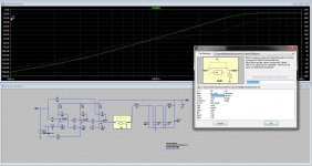
I have found in mine models this one, it contains stuff for simulating gain, open/closed loop.
I will say, just look at it and try. As you see on pic,s I get the same, I need only to change value
for open or closed loop in the measure block, however phase is different, the rest is identical.
It simplifies things further. Good for me.
regards
I will say, just look at it and try. As you see on pic,s I get the same, I need only to change value
for open or closed loop in the measure block, however phase is different, the rest is identical.
It simplifies things further. Good for me.
regards
Attachments
Last edited:
I have play some more with the stuff, I did this idea to get nice response it looks fine, but modulator gain
is now 38dB, I did read the modulator needs not to have that much gain, this is better for linearity, it is
a system modulating who is of itself's not linear.
Plots looks good, I did calculate the points where the poles are, and it does extent the low pass 33dB point
higher, I have nice response until 40Khz.
Strange stuff this class D, the need to linearize so much doe let me thing of the old video recorder who has
limited bandwith because if the video-head speed was low, using a kind of corrections.
I hope the Gan is a really good update for class D.
regards
Attachments
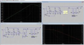
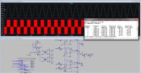
After play, learn some more en testing I get the best results with simulating and look at open en clesed loop.
Using squares does helping me tuning.
After this all, I have to say, go to goal of much as possible gain by tuning the lad/lead circuits. use a
Q 0.5 for low pass did best, I use 24dB octave.
A good trained eye see what look the circuit have.
regards
Using squares does helping me tuning.
After this all, I have to say, go to goal of much as possible gain by tuning the lad/lead circuits. use a
Q 0.5 for low pass did best, I use 24dB octave.
A good trained eye see what look the circuit have.
regards
Attachments
Aloha.
I am a little out of time the last days but have time now.
I have read some more stuff about the way feedback has to be done, it is quite sophisticated stuff but the idea
is so much as possible gain into a stable environment and suppression of feedback ripple.
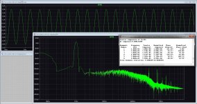
Here I did get with one op amp a response where it looks oke, I get a nice plot where even the low pass resonance point is shifted higher.
I did use only post feedback and it stays stable even with open loop or speaker systems.
Think I get slowly the point how and what to do, er are much o possibilities, but getting it right with less op amps and not cascading stuff is best.
,
I am a little out of time the last days but have time now.
I have read some more stuff about the way feedback has to be done, it is quite sophisticated stuff but the idea
is so much as possible gain into a stable environment and suppression of feedback ripple.
Here I did get with one op amp a response where it looks oke, I get a nice plot where even the low pass resonance point is shifted higher.
I did use only post feedback and it stays stable even with open loop or speaker systems.
Think I get slowly the point how and what to do, er are much o possibilities, but getting it right with less op amps and not cascading stuff is best.
,
Attachments

Hi Kees,
Interesting project here. Hope you and your mother are doing well. I have been listening to some GaN amps and they sound harsh and bright to me. Maybe it’s like anything else and all in the implementation.
Cheers,
X
Interesting project here. Hope you and your mother are doing well. I have been listening to some GaN amps and they sound harsh and bright to me. Maybe it’s like anything else and all in the implementation.
Cheers,
X
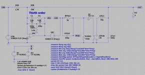
I have now did test, simulate, studied, and see that class d needs extensive correction feedback system who needs to be
made such that gain is high and ripple low, these two things do make it good or not that good. I think class ab do sound better
as class d but can not yet write it that way, I go build one.
I have also try a three level flying cap, I did see that the voltages over the cap does slowly run out and then the fundamental carrier get
less suppressed, looks like delay differences are the cause, I go see if I can make a servo feedback who will correct it.
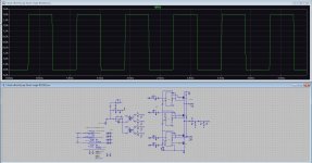
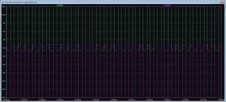
Here on pics I get with a feedback as you see quite low distortions and a nice square test with just one op amp, less op-amp,s
better sound. I did use a post feedback lead corrector, a low pass feedback and op amps with zero and 2 poles, it does act as a thirth order
corrector a la PID.
made such that gain is high and ripple low, these two things do make it good or not that good. I think class ab do sound better
as class d but can not yet write it that way, I go build one.
I have also try a three level flying cap, I did see that the voltages over the cap does slowly run out and then the fundamental carrier get
less suppressed, looks like delay differences are the cause, I go see if I can make a servo feedback who will correct it.
Here on pics I get with a feedback as you see quite low distortions and a nice square test with just one op amp, less op-amp,s
better sound. I did use a post feedback lead corrector, a low pass feedback and op amps with zero and 2 poles, it does act as a thirth order
corrector a la PID.
Attachments
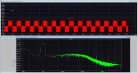
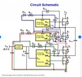
After tuning the class d amp for highest open loop gain and lead/lag factor right for cleanest square with a three level
btl version I did get this.
Ik go build and test now, not the btl but start with single output with this feedback scheme.
Sim is good but say not much about sound quality, but who knows.
The amp does work stable, also with open output or difficult speaker system, I can get distortion even better but then things go badly wrong
with instability.
regards
Attachments

Hi All
A new question, if someone know it, I have when simulating flying cap three level I get running out flying cap voltage
causing a less good suppressed carrier, the voltages go overlap zero volts but need to stay equal on both sides. I did try some solutions but nothing did work well.
It starts oke, but in time it go wrong, overlapping..
Thanks.
Attachments
Hi, simulating power electronic system is not quite the thing for LTSPICE. I would suggest using PLECS. They have free trial license for 1 Month at least and is very user friendly. Also, did you settled on which gate driver to use here? Bootstrapped drivers has limited duty cycle on their high side, until the cap runs out of energy. Isolated driving on the other hand, needs isolated supply and it is quite hard to build one with low common mode noise.
HiHi, simulating power electronic system is not quite the thing for LTSPICE. I would suggest using PLECS. They have free trial license for 1 Month at least and is very user friendly. Also, did you settled on which gate driver to use here? Bootstrapped drivers has limited duty cycle on their high side, until the cap runs out of energy. Isolated driving on the other hand, needs isolated supply and it is quite hard to build one with low common mode noise.
I have seen that delay in the gate drivers are the cause, even when use same type there is always a difference in delay,s that and dead time cause the capacitor drift, only feedback with a PI controller will help then or a delay matching circuit so I can tune it.
There is no problem with the high boot voltages, I have stack the gate drivers and use boot diodes in cascade.
Attachments
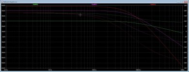
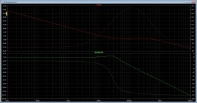
Hi all and @MorbidFractal for his past help.
I have just discover there is a new LTspice who has much better loop simulations with fra.
Can I use these also for loops in class D and normal amps.?.
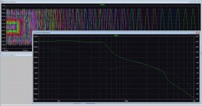
The sim looks oke for me here. I injected the fra between modulator and feedback opamp.
thanks.
I have just discover there is a new LTspice who has much better loop simulations with fra.
Can I use these also for loops in class D and normal amps.?.
The sim looks oke for me here. I injected the fra between modulator and feedback opamp.
thanks.
Attachments

- Home
- Amplifiers
- Class D
- Three level flying cap Gan.