
If anyone has the semi inductance params of the B&C 15DS100 or has that driver and could measure it it'd be greatly appreciated.
The only published impedance data I could find was from the BC website which only had impedance for 20Hz and above, so an assumption has to be made for Re'.
15DS100 LF Drivers - B&C Speakers
15DS100 LF Drivers - B&C Speakers
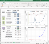
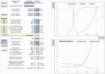
Using rule of thumb (setting Re' = Re*1.1) and removing Re' from the least squares list, a good fit is obtained with the published impedance data for both 4 ohm and 8 ohm versions.
Values from the BC datasheets were used for Sd and VAS.
Attached are exported Semi-Le datasheets and Hornresp driver files for both.
*** Continued thanks to kimmosto for the Curver Tracer utility in VituixCAD ***
15DS100 LF Drivers - B&C Speakers
15DS100 LF Drivers - B&C Speakers
Using rule of thumb (setting Re' = Re*1.1) and removing Re' from the least squares list, a good fit is obtained with the published impedance data for both 4 ohm and 8 ohm versions.
Values from the BC datasheets were used for Sd and VAS.
Attached are exported Semi-Le datasheets and Hornresp driver files for both.
*** Continued thanks to kimmosto for the Curver Tracer utility in VituixCAD ***
Attachments
-
 BC_15DS100-4.png81.3 KB · Views: 167
 -
 BC_15DS100-4_SemiLe.png89.4 KB · Views: 158
 -
BC_15DS100-4_TSP.txt484 bytes · Views: 128
-
BC_15DS100-8_TSP.txt484 bytes · Views: 98
-
en-lf-drivers-15ds100-8.pdf881.6 KB · Views: 122
-
en-lf-drivers-15ds100-4.pdf880.8 KB · Views: 118
-
BC_15DS100-8_Hresp.txt227 bytes · Views: 108
-
BC_15DS100-4_Hresp.txt227 bytes · Views: 109
Last edited:
i'm currently working on a tapped horn using this driver and this helps me greatly, thanks!The only published impedance data I could find was from the BC website which only had impedance for 20Hz and above, so an assumption has to be made for Re'.
15DS100 LF Drivers - B&C Speakers
15DS100 LF Drivers - B&C Speakers
Using rule of thumb (setting Re' = Re*1.1) and removing Re' from the least squares list, a good fit is obtained with the published impedance data for both 4 ohm and 8 ohm versions.
Values from the BC datasheets were used for Sd and VAS.
Attached are exported Semi-Le datasheets and Hornresp driver files for both.
*** Continued thanks to kimmosto for the Curver Tracer utility in VituixCAD ***
Hello everyone,
I'm looking for semi-Le data for some 18"woofers.
I wrote to 18sound and they sent me some more data than the usual T/S-parameters; but I don't know if the semi-Le-parameters needed for Hornresp are hidden somewhere in there or can be calculated from the data I have now. Any help would be appreciated, thanks!
Attachments
I thought the challenge was varying L with amplitude. Varying L with frequency seems taken care of by the most basic impedance sweeps, no?
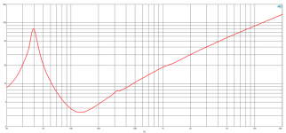
Unfortunately no. You need a plot of impedance vs frequency to determine the Semi-Le Parameters. Example below.I don't know if the semi-Le-parameters needed for Hornresp are hidden somewhere in there or can be calculated from the data I have now

The purpose of the Semi-Le parameters is to model the large increase in inductance at frequencies below 1kHz where you are trying to design woofer enclosures. The cause is the frequency dependent eddy-current losses in the unlaminated pole piece, first investigated and physical theory proposed by Vanderkooy in 1989. A simple way to think about it is that as you go down in frequency the magnetic field from the VC penetrates further into the iron core. So, the inductance increases as more and more iron is effectively added inside the VC.I thought the challenge was
For example here is a comparison of measurement vs modeling for an HCAA-152 in a 4 ft^3 enclosure. (measurements provided by Josh Ricci. https://data-bass.com)
Traditional TSP modeling predicts a nice rounded response, nothing like the peaked real-world measurements...often called an inductance hump.
The Sem-Le model tracks the real-world response.

Some additional comparisons were posted here:
https://www.diyaudio.com/community/threads/hornresp.119854/post-5408931
If interested in learning more about the Semi-Le model, check out the thread over on the Subwoofer forum.
Semi-le_calc: calculator-for-advanced-inductance-model-incorporating-semi-inductance
If math is your thing, a list of references was attached in Post #15
So Semi Le is a tool for low end modelling of an enclosure, as opposed to the crossover?
Essentially it helps refine the enclosure response vs. simpler Thiele/Small bass models?
Essentially it helps refine the enclosure response vs. simpler Thiele/Small bass models?
Both I would say. And yes-when bless you Chris Strahm LEAP parametricized the inductance, the simulations really tracked what I would measure power response near-field right at the cone. It was quite surprising how much some woofers choked off even above like just 100 Hz with no crossover. Makes me wonder now if anyone is laminating pole pieces to mitigate this? Seems to me someone was but I can't remember who. What does Purifi implement against this problem.So Semi Le is a tool for low end modelling of an enclosure, as opposed to the crossover?
Essentially it helps refine the enclosure response vs. simpler Thiele/Small bass models?
Both I would say.
Well, I can understand how Semi-Le would affect the impedance curve, but as I understand it, it's a constant vs. frequency, so the end result of Semi-Le on the impedance can be measured with a simple impedance sweep, therefore in the end I don't need Semi-Le by itself to get an accurate simulation of the crossover's transfer function, right?
What subtlety am I missing?
Correct. Semi-Le parameters are NOT for use with crossover design programs.
Crossover simulation programs use the measured impedance data directly, so there is no reason for a blocked impedance model.
The Semi-Le Parameters are for use with enclosure modeling programs like Hornresp, VituixCad, and SoundEasy which are able to handle a blocked impedance model other than the traditional 2 parameters of Re and Le.
Last edited:
No; I don't need a plot. I just need the five semi-Le-parameters for Hornresp 🙂Unfortunately no. You need a plot of impedance vs frequency to determine the Semi-Le Parameters. Example below.
View attachment 1405826
I know the theory; I even have semi-le_calc running (which I can't get to work as it should, but that's another problem); and what I want to do is optimize the not-yet-existing enclosure of a speaker-to-be-built and find out, which driver(s) fits best.
I know the possible differences in the simulations. At the moment I just have the possibility to use or not use "lossy Le" in Hornresp and the differences are huge; which is why I want semi-Le-data to get better results.
So my question was and still is:
Is there a way to get/calculate these five semi-Le-parameters from the additional data that 18sound provided? (see attachment at my first post)
If not, then my next question would be if there's a fast/easy/automated way to get the data from impedance-plots (often provided by the manufacturers) into text-files for semi-Le_calc. Else I'll try to persuade ChatGPT to do this for me 😛
Thanks,
Kalle
I see the plots of impedance with the two different models. Please forgive me for asking a very naive question, but in terms of the cabinet models... would this not imply that the cabinet models would be affected by Zobel networks? That is, given a driver with significant Semi-Le, and an ideal Zobel to alter the Z above Fs, would the Zobel be unable to fix the problems?
I know in my own argument that the classic Zobel works above Fs, just wondering out loud.
Thanks!
I know in my own argument that the classic Zobel works above Fs, just wondering out loud.
Thanks!
The Zobel network is in parallel with the woofer, so the amplifier will see a different total impedance.
However, the voltage applied to the woofer is unchanged, so the current thru the woofer (red arrow) is unchanged.
The motor force is proportional to current thru the voice coil, so adding the Zobel network will not change the response.

However, the voltage applied to the woofer is unchanged, so the current thru the woofer (red arrow) is unchanged.
The motor force is proportional to current thru the voice coil, so adding the Zobel network will not change the response.
Last edited:
You need the plot to use as input to determine the Semi-Le parameters. If you have a plot you can post, I was offering to calculate the Semi-Le parameters for you.No; I don't need a plot. I just need the five semi-Le-parameters for Hornresp
No, there is not enough information provided.Is there a way to get/calculate these five semi-Le-parameters from the additional data that 18sound provided? (see attachment at my first post)
Yes, you can use the SPL Tracer tool in VituixCAD as I did in Post #25.If not, then my next question would be if there's a fast/easy/automated way to get the data from impedance-plots (often provided by the manufacturers) into text-files for semi-Le_calc.
See online manual here: https://kimmosaunisto.net/Software/VituixCAD/VituixCAD_help_20.html#SPL_Trace
Wow; thank you very much!
I wasted my time this afternoon in trying to write a script to extract the data from such graphics. It doesn't work in any way 🙂
It's not the first loudspeaker I want to simulate and it certainly won't be the last. At the moment, based on the T/S parameters, a dozen drivers from different manufacturers are already possible.
Thank you very much for your generous offer to create the parameters for me, but I don't want to burden other people that much and would rather learn something myself.
I will therefore try out the linked program and will be happy to report back here if I have any problems.
Do we have a shared database other than https://drive.google.com/drive/folders/1i3C9MVA2yDmiwn0ZZT88yXBCjQHjMaE8 ?
Then I would enter the calculated speaker parameters there and make them available to others...
Thank you again!
Kalle
It worked for a first driver; fantastic.
The simulation with Hornresp confirms the expectations/fears that I had based on the posts I have read here and elsewhere: a reduction of more than one dB in the 60Hz - 100Hz range compared to the data without semi-le-parameter.
Semi-Le_calc calculates a value of 7538 for Rss; that seems pretty high to me. Unfortunately, the values read in for the impedance curve only start at 20Hz; could that be a cause?
The driver is LaVoce SAF184.03, btw.
- Home
- Loudspeakers
- Multi-Way
- Thread for Drivers with Semi Inductance