Just curious if anyone has built/analyzed anything like the original push-pull series feedback IT circuit.

Doing a bunch of spice modelling with some different pentodes, the surface level analysis looks good, but two troublesome issues stand out:
1) The 0.1uF capacitors in the feedback path cause a huge increase in gain at low frequency as the feedback trails off. If the interstage can pass frequencies below 10 hz, feels like things could be problematic. I had to go up as high as 3.3uF in some cases to kill the hump down in the 3-5 Hz range. Certainly you can get caps that size but it feels a little ugly to have both an interstage and also caps large enough that they probably have to be metallized.
2) I have some bifilar interstages I was thinking about using if I did try to build it, but it looks like this circuit is not going to be ideal for inter-winding capacitance no matter what, as the lowest AC voltage you could put on the wires that are physically at the center of the winding would be the voltage grid-to-grid for the drivers. The voltage swing on the feedback dividers is very large so you'd essentially setup the secondary to 'drive' the feedback path while the grids are the ground side of the windings.
Probably the answer is 'Don't do it, this is not worth it.' Since you have really high drive voltage through the IT, you'd basically have to build a driver setup powerful enough to drive an IT at low distortion and enough voltage for big power triodes anyway. You'll have basically built a monster PP driver that could just drive PP 300B's anyway. In theory the series connection doesn't present much load to the IT, but Rp of the driver is still going to dominate distortion through the IT, plus whatever the parasitics I mentioned above are doing.
Since C is part of the NFB loop, there will be peaking. Instead of increasing the value of C,
the values of R1 and R2 could be increased by the same factor, keeping their ratio constant.
the values of R1 and R2 could be increased by the same factor, keeping their ratio constant.
Fair enough on the capacitor and resistor divider values. I'm curious about how that will interact with the various parasitics. I need a better model of a PP interstage transformer.
Hi all,
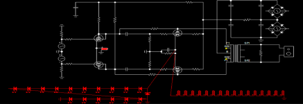
so, has anoyne built the "practical inverse-feedback circuit" proposed by OH Schade on pg 41 of his article? (picture attached)
I did it last evening and this morning, using a small LL1540 1+1:1+1 input transformer, a pair of 4P1L, 130k on R2, 13k on R1 and 150nF for C - and omitted C'. Very soon I had a ~100khz oscillator.
I went back to the paper and found some explanation on C'. "a possible phase reversal due to leakage-reactance tuning of the input transformer is prevented by connecting small condensers across each secondary winding". I had soms 2nF handy, put them in, and...
- ErikdeBest
- Replies: 3
- Forum: Tubes / Valves

I've had astounding success by doing series feedback to the previous stage cathode. It's so simple and just so good. You can do much more feedback if you want to.
Schade's circuit was interesting for showing some curves in a white paper, but it's just pretty complex for what it does. But it could be fun to build too.
Schade's circuit was interesting for showing some curves in a white paper, but it's just pretty complex for what it does. But it could be fun to build too.
I did it just like OA's paper in an amp with IT's. Worked just fine but I went back to triode connected output tubes and took out the "Schade" feedback. Less power but I liked it.
I have done some tyest without trafos.
In the original circuit the explanation is very general; so who want to built one similar need to have a good test set to check in deep the performance.
With some triode as driver, without OT it seems a bad solution for output stage. Also using different types.
I would like to test with pentode but not sure.
There is a good notes on one Philisp book.
Then with test to maximize the circuit I decided to use.
Using some strange kind of mixture with sand and tube adding three or four type of feedback is not my goal.
One example of what I mean is here:

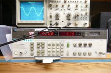
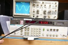
This is a freq. answer of an amp with 4 x 300B in p-p
With and without FB; 10 dB of FB that I normally use.
Red is without and blue is FB

The BW is...
post nr. 46
""""""""""""""
As Robert Gribnau wrote in another thread:
See for an explanation of this effect pages 396 to 399 of this book:
Fundamentals of Radio Valve-Technique, Deketh, Philips, 1949
"""""""""""""""""""""""""""""
IF in the 80 years nobody of the greatest manifacturer built something similar one reason exist.
In the original circuit the explanation is very general; so who want to built one similar need to have a good test set to check in deep the performance.
With some triode as driver, without OT it seems a bad solution for output stage. Also using different types.
I would like to test with pentode but not sure.
There is a good notes on one Philisp book.
In general, I always search to get the best results using the best components available and, for power amp, the first one is OTBut it is fun for us, and sometimes the journey is as important as the result
Then with test to maximize the circuit I decided to use.
Using some strange kind of mixture with sand and tube adding three or four type of feedback is not my goal.
One example of what I mean is here:
This is a freq. answer of an amp with 4 x 300B in p-p
With and without FB; 10 dB of FB that I normally use.
Red is without and blue is FB
The BW is...
post nr. 46
""""""""""""""
As Robert Gribnau wrote in another thread:
See for an explanation of this effect pages 396 to 399 of this book:
Fundamentals of Radio Valve-Technique, Deketh, Philips, 1949
"""""""""""""""""""""""""""""
IF in the 80 years nobody of the greatest manifacturer built something similar one reason exist.
HiJust curious if anyone has built/analyzed
have you done some investigations?
Walter
I believe Marantz (models 8 & 9) and Harmon Kardon both used it.IF in the 80 years nobody of the greatest manifacturer built something similar one reason exist.
I don't think so; I will check, I know the stuff but many years are passed !!I believe Marantz (models 8 & 9) and Harmon Kardon both used it.
Walter
This series Fdbk with an interstage xfmr seems to be mainly a conceptual scheme and not so practical. The classical amplifiers that did this shortened loop stuff just put a resistor from the output plate back to a driver stage cathode or grid (crossed). If that is too much N Fdbk, then just use a higher value resistor. Easier DC arrangement and easy drive capabilities, without frequency penalty or cost. .
Just spice modelling like I discussed in the first post. The LF bump, the parasitic situation, and the overall demands on the IT & driver make it seem not super attractive to persue. I still may try and measure this thing if I end up building a new PP amp instead of SE, I have to finish my speakers and see how much power I'm actually going to need in my listening room.Hi
have you done some investigations?
Walter
I have made in the past a very powerful balanced Shade with 6CA7 connected as a pentode, driven by 6EJ7 pentodes connected as a triode. It had x34 gain and was sensitive to the noise of the pre connected to the input... The simulated scheme included, but not actually tested, a row of infrared LED diodes as a common cathode load on the 6CA7 to reduce low frequency memory or crossover distortion.
Attachments
I have an idea after lot of real test but some other are coming to have a final consideration.The LF bump, the parasitic situation, and the overall demands on the IT & driver make it seem not super attractive to persue
Walter
Schade's original paper proposed that providing feedback from the plate of a 6L6 tube to its grid would allow for triode like curves. The usual audio amps of the time period involved interstage transformers and capacitors, and silicon based life forms did not yet exist. This required applying the audio drive and the feedback signal to the same electrode of the output tube.
I spent quite a bit of time with TV sweep tubes and mosfets and a bit of LT Spice before coming up with something I called UNSET. SET for Single Ended Triode, and UN because there are no triodes used. TV sweep tubes can make a lot of power, but they cannot generally be conventionally triode strapped because of their low screen grid voltage rating.
One simply uses a resistive voltage divider from the plate to ground with the divided voltage fed to the control grid. Ground the drain of a P channel mosfet, connect its source to the cathode and feed the audio drive signal to the gate. This results in near perfect triode curves.
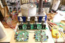
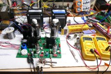
I have been using this circuit as my Go-To output stage for both SE and push pull amps up to 500 watts. The single board used a pair of big sweep tubes to provide 25 WPC. The picture of one driver board feeding two octal output boards produces over 500 watts of audio at 3.8 % THD. The circuit shows a prototype of an early UNSET SE amp design. I have since redesigned the driver stage for more gain at near zero THD. See the UNSETURATOR circuit.
The triode curves are hand traced with variable power supplies and an analog current meter. They are not extremely accurate but show the type of curves generated by this method. The screen grid supply is completely independent of the "Schade feedback" so that any tube can be used at the optimum screen voltage that it needs. Most of the sweep tubes I used in these experiments were run on a fixed 175 volt supply. The cathode usually idles in the 30 to 60 volt range depending on the tube and B+ supply used, but it swings from near zero to twice the idle voltage at full power output, so the "cathode bias" voltage is not wasted in a resistor.
The mosfet in the cathode is a follower which is sonically benign. For those who prefer not to put silicon in anywhere near the signal path, one can use a driver transformer in the cathode, preferably with a DCR suitable to set the bias voltage, but considerable drive power is required to do this. I have a guitar amp design that uses all old school parts and all metal cased vacuum tubes. I am currently running a pair of 6F6 tubes to drive a pair of 6L6 tubes for about 35 watts of power. This is just a first "proof of concept" test. I will try several other ideas before deciding on the final design.
I just returned from the Dayton Hamfest with a 40 pound box full of assorted untested metal tubes. Lots of real old tubes in that box.
I spent quite a bit of time with TV sweep tubes and mosfets and a bit of LT Spice before coming up with something I called UNSET. SET for Single Ended Triode, and UN because there are no triodes used. TV sweep tubes can make a lot of power, but they cannot generally be conventionally triode strapped because of their low screen grid voltage rating.
One simply uses a resistive voltage divider from the plate to ground with the divided voltage fed to the control grid. Ground the drain of a P channel mosfet, connect its source to the cathode and feed the audio drive signal to the gate. This results in near perfect triode curves.
I have been using this circuit as my Go-To output stage for both SE and push pull amps up to 500 watts. The single board used a pair of big sweep tubes to provide 25 WPC. The picture of one driver board feeding two octal output boards produces over 500 watts of audio at 3.8 % THD. The circuit shows a prototype of an early UNSET SE amp design. I have since redesigned the driver stage for more gain at near zero THD. See the UNSETURATOR circuit.
The triode curves are hand traced with variable power supplies and an analog current meter. They are not extremely accurate but show the type of curves generated by this method. The screen grid supply is completely independent of the "Schade feedback" so that any tube can be used at the optimum screen voltage that it needs. Most of the sweep tubes I used in these experiments were run on a fixed 175 volt supply. The cathode usually idles in the 30 to 60 volt range depending on the tube and B+ supply used, but it swings from near zero to twice the idle voltage at full power output, so the "cathode bias" voltage is not wasted in a resistor.
The mosfet in the cathode is a follower which is sonically benign. For those who prefer not to put silicon in anywhere near the signal path, one can use a driver transformer in the cathode, preferably with a DCR suitable to set the bias voltage, but considerable drive power is required to do this. I have a guitar amp design that uses all old school parts and all metal cased vacuum tubes. I am currently running a pair of 6F6 tubes to drive a pair of 6L6 tubes for about 35 watts of power. This is just a first "proof of concept" test. I will try several other ideas before deciding on the final design.
I just returned from the Dayton Hamfest with a 40 pound box full of assorted untested metal tubes. Lots of real old tubes in that box.
Attachments


Very good but it is a field far from Schade or not?I spent quite a bit of time with TV sweep tubes and mosfets and a bit of LT Spice before coming up with something I called UNSET
And, my personal consideration, with the use of sand in these circut in the signal path the definition of tube amp in not properly.
No doubt on the right perfromances, of course
Walter
Schade's paper discussed feedback from the output tube's plate to its control grid to create triode like curves. He used output tube plate to driver tube plate and other means to avoid the huge DC voltage difference between the plate and grid. Feedback directly from the plate to grid with no reactive components in the path is the purest method of accomplishing this feedback.Very good but it is a field far from Schade or not?
As I mentioned in my post:And, my personal consideration, with the use of sand in these circut in the signal path the definition of tube amp in not properly.
For those who prefer not to put silicon in anywhere near the signal path, one can use a driver transformer in the cathode, preferably with a DCR suitable to set the bias voltage, but considerable drive power is required to do this.
It is possible to put an interstage transformer in the cathode circuit of the output tube to accomplish driving the cathode instead of using a mosfet. I did this in a test amp with good results, but high frequency performance was limited because I used a 60 Hz mains transformer as an interstage.
Everyone is free to use whatever tech they prefer. I have been using the mosfets as followers in tube amps for years. The most important spec for a follower is Gm and a mosfet beats a vacuum tube in that respect. I do not use any silicon in a gain stage for several reasons.
Attachments
I have two personal considerationSchade's paper discussed feedback from the output tube's plate to its control grid to create triode like curves
First is the use of sand with tube inside the signal path will change the definition of the project to Hybrid.
Second, I tested many simple config of Schade.
A s.e. with KT88 triode, different OT and different driver with different % of FB
The impression is that the theory exposed by Schade is valid as he described, in addition, as specified about the interstage trafo, who want to reproduce the circuit need to test carefully the type of trafo ( in fact there aren't any specs about it) so this means that a good test setup is necessary.
Also a beautiful paragraph from a Philips book explain the limit that are, for me, great.
I have planned to test Schade with p-p config but I am quite sure that the results are in the same way.
Last, as wrote in other occasion, if in 80 years nobody of the greatest manifacturer used Schade one reason exist.
Walter
I wouldn’t care too much about using sand. It’s OK for me at least. And of course glass is made of sand as well…
- Home
- Amplifiers
- Tubes / Valves
- Thoughts on the old Schade PP series feedback?