Listen. I have problems with my eyes and I have no more equipment except an old Unaohm and a home-made signal generator.This can be obtained with a proper project without any problems also including the FB loop out-in.
The quality of project and OT is the secret, no way.
And still I can't see a proper test results done on desk.
Walter
If you want to try to build it here is the .asc file. The coil on Gs is essential. Diodes D1 and D2 must be bridge rectifiers. The 27 1N4148 series is to be tried instead of the Rk 270ohm. However, some values should be adjusted based on the type of output transformer used, but it is the starting point.
I do not take responsibility for construction failure.
Attachments
Last edited:
Thx but it is not my interest now.If you want to try to build it here is the .asc file.
I have a lot of stuff to use for Schade config, in case.
But it is interesting that it is difficult to see some real test on lab of this config.
Walter
Have you built it?Here is the cct with 50% NFB.
In case have you check the performances?
Walter
waltube
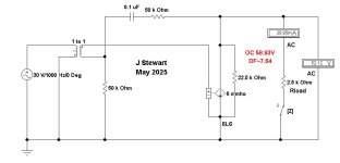
The idea behind this modification of the original circuit is very simple: by adjusting the ratio of the resistor values R 1 vs R 2 (R 1` vs R 2`) both first grids are brought to 0-Vdc potential, and in the same way the value of the local negative reaction from the anodes of the output lamps to the first grids is also adjusted at the same time.
ps, The advantage is that there are no more capacitors connected in series with resistors R 2, but there must be another negative voltage source, in this case it is a -300V source.
Last edited:
I noted now the value you put on circuit.The idea behind this modification of the original circuit
But I think is necessary to test on desk.
And seems to be little complicated including the trafo
Walter
If you mean a small driver transformer then IMHO it's not that complicated because no DC component flows through the secondary windings as long as such an output power stage operates in A1 or AB1 class, but as drawn there is certainly a DC component flowing on the primary side of the driver transformer.
No. Not this point , it is evident that no DC is presentyou mean a small driver transformer then IMHO it's not that complicated because no DC
I think the setting of a proper % of FB will be checked on desk to reach the best performance

AgreeDepending on the choice of the type of output beam power tetrode or power pentode of course various circuit values must be adjusted to optimal values, including the driver transformer, and of course everything here must be tested on a workbench with real elements.
In the my test with different setting I see the enormeous changing in the results.
These are, in final, scarce respect the standard type of FB normally used.
The funny thing is that seems is very difficult to see some complete test lab of a real circuit, s.e. or p-p, to understand what happen .
I am moving now on p-p config after the s.e. , taking some example seen in the forum ; I am happy because there are lot of iron at my disposition so I hope to see something interesting ( but I have a great doubt)
Walter
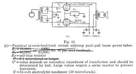
RCA in their handbook published very interesting push-pull amp schematic, with local feedback around output tubes, and around drivers: to anode and cathode of the driver. Perfect approach. I use something similar in my amps.This series Fdbk with an interstage xfmr seems to be mainly a conceptual scheme and not so practical. The classical amplifiers that did this shortened loop stuff just put a resistor from the output plate back to a driver stage cathode or grid (crossed). If that is too much N Fdbk, then just use a higher value resistor. Easier DC arrangement and easy drive capabilities, without frequency penalty or cost. .
Already manufactured an year ago before Schade publication.Used by Philco in their 38-116 receiver, 1938.
Circuit lifted from Beitmans 1926-1938 Most Often Needed Radio Diagrams.
The only circuit of this kind in a reference of 235.
After I get the amp that I am working on completed, I am going to redesign my Unity-Coupled amp so that it consists of two stages only, a CCS-loaded pentode input stage and the output stage. I'll take feedback from the cathodes of the output tubes to the cathodes of the input tubes. It'll be my first nested feedback amp.RCA in their handbook published very interesting push-pull amp schematic, with local feedback around output tubes, and around drivers: to anode and cathode of the driver. Perfect approach. I use something similar in my amps.
My current project is also 2 stages and ~36dB of feedback from output tube plate to input tube cathode. It's a lot of feedback in one loop. I can't provoke any bad behavior but I don't know how much phase margin I have. Unity-gain bandwidth is ~17MHz, though, which scares me a bit. That was in bench testing and as I build I will have to adjust for the new phase response of the new layout.
But it is a lot of FB.My current project is also 2 stages and ~36dB of feedback
In my opinion the best way is to fix a minimum of performances in open loop then apply a low % of Fb to reach a reasonable value of THD, FFT spectrum, response.
That's one approach, and I have done that in the past. The thing I really like about this amp is that the background noise level is far below the other tube amps that I have designed or owned. It really is nice to have no background hiss when paired with very sensitive speakers, even with the ear close to the driver.
If you guys are looking to build, Fender used a similar interstage in their PS300 and PS400 amps. These interstage transformers blow up a lot because of the wacky balance scheme and excessive wattage: 700v on 6550 plates! It probably wouldn't be too hard to test your hypothesis for a few hundred dollars.
A few companies sell a copy of this transformer.
https://www.mercurymagnetics.com/model/300-ps/

A few companies sell a copy of this transformer.
https://www.mercurymagnetics.com/model/300-ps/
But the interstage is out from output circuit and it has around 310 Vdc at anode of 6V6 in triode configIf you guys are looking to build, Fender used a similar interstage in their PS300 and PS400 amps. These interstage transformers blow up a lot because of the wacky balance scheme and excessive wattage: 700v on 6550 plates! It probably wouldn't be too hard to test your hypothesis for a few hundred dollars.
So the 700 V can cause damage if the 6550 goes in short, maybe
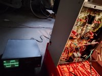
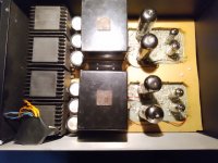
Two photos of that amp; on square wave 10KHz@8ohmThe simulation of the circuit I posted gave the following results
(with infrared diode load//cap, on 6ohm, 590Vak and 300Vgs):
Attachments
- Home
- Amplifiers
- Tubes / Valves
- Thoughts on the old Schade PP series feedback?