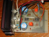
I have since replaced the TL072 in the photo with AD712s.danielwritesbac said:Looking forward to seeing this "assisted" LM1875.
Maybe the circuit can work with LM3886 too?
Can you post the photo?
Attachments
Hi paulb:
Can you email me the article, maybe I can help you with a new pcb.
I'm just a rookie, but I persist to learn.
Cheers
Iván
Can you email me the article, maybe I can help you with a new pcb.
I'm just a rookie, but I persist to learn.
Cheers
Iván
You'll have to email me so I can email an attachment to you. It will take a few days for me to find the time to scan the article.
paulb said:
I don't, except maybe a paper copy of the pattern (I'll look). The schematic shows a bridged version with servo DC feedback; you could simplify it to just the composite amp itself. It was from a Popular Electronics article, I think, from long ago, I will check for this as well.
Are you living in the Snowbank they just auctioned off?
No such luck! This ones still here and will be for some time. Some people call this snowbank a 🤐hole, others call it Winnipeg.😉
As for the Lm1875 stuff I'll take whatever you can send. I'll email you my email.
I like your idea of simplify. I complicate things all the time.
Hello again paulb,
I can't email you my email. Not enough posts I guess.
You can email me here: bobsled69 .at. hotmail.com.
Thanks
I can't email you my email. Not enough posts I guess.
You can email me here: bobsled69 .at. hotmail.com.
Thanks
Has anybody tried. . . tossing the 22uf?
Hey, I was wondering about replacing the 22uf cap (zobel for the gainclone loop) with a plain ordinary wire jumper, so that only the 10k R is in use.
That does two things:
It grounds DC out of the loop.
It makes slightly (very slightly) higher DC offset.
For the larger gainclones, this warms up the sound and cools off the chip. Has anybody tried it with the baby?
That will eliminate the Zobel network, which could make the amp unstable. Under some circumstances this will cause oscillation. Not recommended.
shorting out the cap eliminates the Zobel.
Instead it adds the 10r in parallel to the load.
8ohm speaker becomes equivalent to 4.4ohm speaker.
I would never expect reducing the load value like that to make the amp run cooler!
Instead it adds the 10r in parallel to the load.
8ohm speaker becomes equivalent to 4.4ohm speaker.
I would never expect reducing the load value like that to make the amp run cooler!
I guess that yours is different than my spec sheet? Mine is 10K ohms not 10 ohms. That's so much different. OH!!! Hey, I meant the zobel for the loop, not the zobel for the speaker.
that's not a Zobel nor is it a gainclone loop.
You are referring to the NFB with the DC blocking capacitor.
You are referring to the NFB with the DC blocking capacitor.
Thanks to PaulB I made a new pcb minimalist design of the version #4, a 10W inverting composite, because this is not the original thread I email everyone who want it.
Cheers
Iván
Cheers
Iván
AndrewT said:that's not a Zobel nor is it a gainclone loop.
You are referring to the NFB with the DC blocking capacitor.
I'm not referring to blocking DC.
There is already DC blocking via input filter decoupling cap, and there is already AC shunting via the zobel on the speaker output. Not talking about either one.
Aren't we taking about LM1875? From pins 2 to 4, there's a fixed l-pad structure of resistors, pass of 100k, shunt of 10k.
However, my schematic has a 22uf cap between the 10k and the ground. It is shunting AC.
This is no longer a pure signal because it is modified many, many times by the presence of that capacitor shunting AC (music) at specific frequencies during amplification. That's a noise.
Furthermore, the value of the cap doesn't go in proportion to the value of the l-pad structure between different models of Overture chip amp.
So, not only is it a curious thing to do (make a noise during each pass of a copy, of a copy, of a copy sort of situation), but the recommended capacitor isn't consistent in proportion between models. So, the recommended bandwidth of this noise varies.
That's altogether puzzling.
danielwritesbac said:I'm not referring to blocking DC.
However, that is one function of what the cap you are on about does. It reduces the gain at DC down to unity so that any input offset voltage does not result in a larger DC offset at the output.
richie00boy said:
However, that is one function of what the cap you are on about does. It reduces the gain at DC down to unity so that any input offset voltage does not result in a larger DC offset at the output.
Of course. Either way it is minute.
I'm referring to BrianGT's www.chipamp.com lm3886tf with specific directions that this specifc cap should be left off because it makes an awful sound.
One possible difference is that the fixed l-pad structure on lm3886 is 22k against 680 ohms wheras the lm1875 has 100k against 10k. The 22k version has a much firmer grip than the loosey-goosey hum-prone 100k structures. So, there's a possible difference.
The other possible difference is the fact that one is a gain of 11 and the other is a gain of 33, i.e. one has orders of magniture more feedback than the other.
Also, were you comparing the LM3886 with 22k/680 against the LM1875 with 100k/10k? Or was it the LM1875 in both cases?
Also, were you comparing the LM3886 with 22k/680 against the LM1875 with 100k/10k? Or was it the LM1875 in both cases?
I'm willing to bet that each of the amps has at least two high pass filters built into them and that these HP filters are different in every case.
With those presumed differences the bass is bound to be different sounding.
With those presumed differences the bass is bound to be different sounding.
paulb said:For you LM1875-heads: ever considered a composite amp design?
Hi Paul,
I'm really glad to see someone mentioning composite designs for chipamps. I've been playing with them in LTspice for a year or so, in my spare time (but had to resort to using a TI OPA541 spice model (E-version), since there don't seem to be any good models for the National chipamps). My real work has gotten in the way of contructing any of them, for quite a while now. But I'm hoping to finally be able to try building some more of my designs, within the next month or two.
The first thing I noticed, after wrapping an opamp's feedback loop around a chipamp, was that the THD could be made almost arbitrarily low. I have many designs that have THD @ 20 kHz that's less than .0001% (and much lower, for all lower frequencies). It's also possible to simultaneously be able to drive large capacitive loads, with no overshoot or ringing, for squarewave inputs, using output slew rates that are the maximum the chipamp can provide (but not try to push it any faster). It should be interesting to find out how they sound.
I eventually was able to simulate them with fairly-detailed models, including models of speakers, models of speaker cables, models of real power supplies that use models of measured transformers and even models of the mains supply, including parasitics everywhere, even down to including the parasitic inductances and resistances of wires and PCB traces. (With LTspice, I was also able to use WAV files of music for the simulated circuits' inputs, and create WAV files from the outputs. 🙂
When simulating composite chipamp circuits, I found it fascinating to look at the signal being sent to the chipamp, with, for example, a squarewave at the main input. The outer feedback loop "knows" to add sharp peaks at the squarewave's rise and fall points, to improve the chipamp's output squarewave, and everything can be fine-tuned to get the best-possible edges out of the chipamp, but with no overshoot or ringing.
I've also done some chipamp designs that use Hawksford-style "error correction" topologies, where, basically, opamps in an outer feedback loop subtract the input from the output to get an "error" signal, which is then subtracted from the input to the chipamp. Some of the best of those even phase-shifted (delayed) the input signal (for the feedback loop) to try to get it better time-aligned with the output feedback before the error signal was derived, and used super-fast opamps in the feedback loop, to minimize time-alignment errors.
I'm also a fan of DC Servos, and have done quite a bit of work on different designs, for them, mainly in trying to get the AC response down to almost nothing, at very low frequency, while still maintaining a reasonably-fast response time. There is a thread, here, somewhere, with some of the initial ones, which includes links to the LTspice files for them.
There's some good stuff about composite amplifiers, in general, in Walt Jung's "Op Amp Applications Handbook", which is available as a free download from the Analog Devices website, at:
http://www.analog.com/library/analogDialogue/archives/39-05/op_amp_applications_handbook.html
Sorry to have blathered-on, for so long, about all of that. Carry on.
- Home
- Amplifiers
- Chip Amps
- Thoughts On LM1875 Gainclones