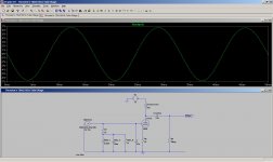
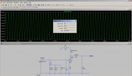
Thanks to kevinkr who shared his tube libraries and also guided me towards LTSpice, I did my first LTSpice simulation using Thorsten's tube stage from post #1.
However, I am rather confused that why 😕 I am getting 14v PP and the output.
Here is the screen shot and LTSpice file, kindly take a look (zip folder has LTSpice file) and guide me what I am doing wrong. I suspect something is off with units.
However, I am rather confused that why 😕 I am getting 14v PP and the output.
Here is the screen shot and LTSpice file, kindly take a look (zip folder has LTSpice file) and guide me what I am doing wrong. I suspect something is off with units.
Attachments
@chanmix51
As is customary when all his technical objections are met ThorstenL attempts to move the focus of an argument to a subjectivist position with no verifiable foundation.
Take heart, however, from the following quote from Douglas Self:
'nods to Subjectivist convention are unlikely to damage real performance; this is however not the case with some of the more damaging hypotheses, such as the claim that negative feedback is inherently harmful'
Actual performance which is the "listening" in case of audio is verification of subjectiveness!
I learned this thing when,
1) I went to hear technically superior (I believed) loudspeaker (electrostatic loudspeaker) and it turned out to be so so.. Salesmen brought in another speaker (less cheaper cone driver one) and I was sold in 10ms.
2) My old DAC, that was five times the price, technical performance and build quality of a used DAC, was beaten in listening.
I think audio is like financial markets where subjectivity rules. If you have a stock/bond/commodity about which God (absolute technical truth) has told you that it is worth $1 billion but markets do not think so then it is worth nothing 🙄. On the other hand, if markets think that your shoe is worth $2 billion then it is $2 billion. In case of audio, you can substitute God with Audio Precision test instrument and markets with audiophile.
These are my personal believes (these days 😉) and thus no fights 😀
Hi,
Hardly. The various TECHNICAL problems with looped feedback have been well documented since the days of Baxandall, Ottala and Hawekesford.
I have no interest to write a review of the available material, so please do this yourself.
Well, then also take heart in the fact that according to D. Self the NE5532/NE5534 is already pretty much the best audio amplifier there ever was, is and will be, so if you want to be a follower and believer of Mr. Self, why bother with anything else but a 5534?
Ciao T
As is customary when all his technical objections are met ThorstenL attempts to move the focus of an argument to a subjectivist position with no verifiable foundation.
Hardly. The various TECHNICAL problems with looped feedback have been well documented since the days of Baxandall, Ottala and Hawekesford.
I have no interest to write a review of the available material, so please do this yourself.
Take heart, however, from the following quote from Douglas Self:
'nods to Subjectivist convention are unlikely to damage real performance; this is however not the case with some of the more damaging hypotheses, such as the claim that negative feedback is inherently harmful'
Well, then also take heart in the fact that according to D. Self the NE5532/NE5534 is already pretty much the best audio amplifier there ever was, is and will be, so if you want to be a follower and believer of Mr. Self, why bother with anything else but a 5534?
Ciao T

Hi,
First put some extra viewpoints on to measure also the input to the tube.
I would suggest that either your stimulus is wrong (maybe you mistook peak for RMS when entering numbers?) or the 6DJ8 Model is wrong.
Placing the extra viewpoints will make clear which it is.
In theory real 6DJ8's have a Mu of around 30 and with 4mA Peak-Peak and 47 Ohm we get 0.188V Peak-Peak, multiplied by the gain of 30 it gives 5.64V Peak-Peak or 1.994V RMS...
Ciao T
Thanks to kevinkr who shared his tube libraries and also guided me towards LTSpice, I did my first LTSpice simulation using Thorsten's tube stage from post #1.
However, I am rather confused that why 😕 I am getting 14v PP and the output.
First put some extra viewpoints on to measure also the input to the tube.
I would suggest that either your stimulus is wrong (maybe you mistook peak for RMS when entering numbers?) or the 6DJ8 Model is wrong.
Placing the extra viewpoints will make clear which it is.
In theory real 6DJ8's have a Mu of around 30 and with 4mA Peak-Peak and 47 Ohm we get 0.188V Peak-Peak, multiplied by the gain of 30 it gives 5.64V Peak-Peak or 1.994V RMS...
Ciao T
Hi,
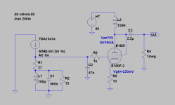
For fun you could try using the E180F triode connected and with the I/V circuit scaled to give you the desired output. For 2V out the I/V resistor becomes 27R and the LCR for the anti-sinc filter scale suitably. The E180F will have lower noise than the 6922 and NOS E180F are not difficult to get and do not quite carry the same silly pricetags as NOS 6922 style tubes.
Based on the Mullard Triode curves the operation will be 75V/12mA, gain is around 50 if CCS or Choke loaded. Output impedance will be around 2.5K.
So the Tango TC-160/15W Choke will be usable as Anode Load choke, otherwise Magnequest may have a suitable item or a CCS (IXYS 10M450 preferred) can be used. It is important to orient the chokes for lowest Hum.
Ciao T
Hi Thorsten,
I find really interesting in trying the E180F in triode mode with a gyrator load perhaps.
Can you explain the LCR filter stage calculation please?
Thanks
Ale
Hi,
Simple, just scale elements in the LCR circuit by the ratio of the I/V resistor in the original schematic and the new one.
So, if you go for 23.5 Ohm I/V which is 0.5 times the original you must multiply resistor and inductor values by that factor, while you must divide capacitors value by this factor.
So for 27R instead of 47R multiply the the resistor and inductor value by 0.575 and divide the capacitor value by 0.575 and use nearest preferred value.
Ciao T
Can you explain the LCR filter stage calculation please?
Simple, just scale elements in the LCR circuit by the ratio of the I/V resistor in the original schematic and the new one.
So, if you go for 23.5 Ohm I/V which is 0.5 times the original you must multiply resistor and inductor values by that factor, while you must divide capacitors value by this factor.
So for 27R instead of 47R multiply the the resistor and inductor value by 0.575 and divide the capacitor value by 0.575 and use nearest preferred value.
Ciao T
Hi,
First put some extra viewpoints on to measure also the input to the tube.
I would suggest that either your stimulus is wrong (maybe you mistook peak for RMS when entering numbers?) or the 6DJ8 Model is wrong.
Placing the extra viewpoints will make clear which it is.
In theory real 6DJ8's have a Mu of around 30 and with 4mA Peak-Peak and 47 Ohm we get 0.188V Peak-Peak, multiplied by the gain of 30 it gives 5.64V Peak-Peak or 1.994V RMS...
Ciao T
Thanks Thorsten.
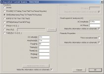
Here are the pictures of new results for which I used DC offset of -2mA, Amplitude of -1mA (in LTSpice Amplitude is defined as "the undamped amplitude of the sinusoid; i.e., the peak value measured from zero no DC offset value"). Here is my understanding. -2m DC offset represent digital silence and thus the output of TDA1541A modulates around -2mA instead of 0mA. Thus -4mA Peak to Peak becomes -2mA Peak to Peak (-4mA less -2mA DC offset) and becomes -1mA peak to be used in LTSpice as defined by LTSpice definition of amplitude. Am I correct or just misjudging.
Using these value in LTSpice, I get DC operating point of -94.002mV on grid of 6DJ8 and 2.3398V at output.
Attachments

Last edited:
Hi,
I don't use LT Spice, but something sounds still wrong.
The DC offset is now right, but the Peak value should be 2mA, in other words a full scale sinewave covers 0mA to -4mA.
What is the AC input voltage to the 6922?
Ciao T
Here are the pictures of new results for which I used DC offset of -2mA, Amplitude of -1mA (in LTSpice Amplitude is defined as "the undamped amplitude of the sinusoid; i.e., the peak value measured from zero no DC offset value"). Here is my understanding. -2m DC offset represent digital silence and thus the output of TDA1541A modulates around -2mA instead of 0mA. Thus -4mA Peak to Peak becomes -2mA Peak to Peak (-4mA less -2mA DC offset) and becomes -1mA peak to be used in LTSpice as defined by LTSpice definition of amplitude. Am I correct or just misjudging.
I don't use LT Spice, but something sounds still wrong.
The DC offset is now right, but the Peak value should be 2mA, in other words a full scale sinewave covers 0mA to -4mA.
What is the AC input voltage to the 6922?
Ciao T
...according to D. Self the NE5532/NE5534 is already pretty much the best audio amplifier there ever was
...and when his strategy is exposed he moves to gross exaggeration, misrepresentation and ad hominem.
Hi,
You have read Self's articles and books, right? If so, I can save myself the quotes.
Now if with all respect, if I truthfully state someone's opinion, as presented repeatedly, over decades, in print and you call that "gross exaggeration, misrepresentation and ad hominem", what does that make you?
Somehow the words "Pot, Kettle, Black" appear in my mind...
It would seem that in fact you engage in the precise tactics you accuse me of using, when in fact I am not.
Ciao T
...and when his strategy is exposed he moves to gross exaggeration, misrepresentation and ad hominem.
You have read Self's articles and books, right? If so, I can save myself the quotes.
Now if with all respect, if I truthfully state someone's opinion, as presented repeatedly, over decades, in print and you call that "gross exaggeration, misrepresentation and ad hominem", what does that make you?
Somehow the words "Pot, Kettle, Black" appear in my mind...
It would seem that in fact you engage in the precise tactics you accuse me of using, when in fact I am not.
Ciao T
However, I am rather confused that why 😕 I am getting 14v PP and the output.
L=160H
No series resistance!
Typical resistance are 200-400 ohm.
With 300R resistance output RMS 2.7V.
L=160H
No series resistance!
Typical resistance are 200-400 ohm.
With 300R resistance output RMS 2.7V.
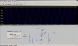
Thanks and Thanks to Thorsten too. I added 300 Ohm to inductor but same results. I think Thorsten is right, my source is not correct and I am doing a great unknown (at least to me) blunder in LTSpice.
Please see the first screen shot. With -2mA DA offset and 2mA peak, the Peak to Peak current is 4mA, however, as it can bee seen in second screen shot that strangely the RMS is very high at 2.4494mA instead of 1.414mA.
Can someone please help me fix whatever is going on in LTSpice?
Attachments
Hi,
What is the P-P voltage directly at the I/V Circuit, before the tube?
Ciao T
Can someone please help me fix whatever is going on in LTSpice?
What is the P-P voltage directly at the I/V Circuit, before the tube?
Ciao T
Hi,
Simple, just scale elements in the LCR circuit by the ratio of the I/V resistor in the original schematic and the new one.
So, if you go for 23.5 Ohm I/V which is 0.5 times the original you must multiply resistor and inductor values by that factor, while you must divide capacitors value by this factor.
So for 27R instead of 47R multiply the the resistor and inductor value by 0.575 and divide the capacitor value by 0.575 and use nearest preferred value.
Ciao T
Hi Thorsten,
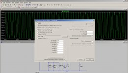
Many thanks. See attached simulation. Seems ok with a gain of about 34.74dB and producing an output of 2Vrms. Left bias point to -0.22V where the gm is quite high. will you reduce the bias? Anode current is 16mA with 75V - at least that is what you get with the spice model around.
What is the role of C2 here?
Also added a grid stopper as well.
If everything is ok, will replace the anode choke with a gyrator...
Thanks
Ale
Attachments
Hi,
Sounds all on da money.
Ultra-ultrasonic rolloff. Scale the same way as the Cap for the LCR.
Try keeping it at 100 Ohm or less (I often use 10R AB or Xicon Carbon Composition resistors), otherwise you add too much noise. If you feel adventurous use only ferrite beads directly on the tube pins.
Ciao T
Many thanks. See attached simulation. Seems ok with a gain of about 34.74dB and producing an output of 2Vrms. Left bias point to -0.22V where the gm is quite high. will you reduce the bias? Anode current is 16mA with 75V - at least that is what you get with the spice model around.
Sounds all on da money.
What is the role of C2 here?
Ultra-ultrasonic rolloff. Scale the same way as the Cap for the LCR.
Also added a grid stopper as well.
Try keeping it at 100 Ohm or less (I often use 10R AB or Xicon Carbon Composition resistors), otherwise you add too much noise. If you feel adventurous use only ferrite beads directly on the tube pins.
Ciao T
Fantastic, thanks Thorsten. Will reduce C2 and change grid stopper. May try ferrite beads though...
Now I need to read the huge number of threads and posts around the TDA1541a...
Just need to get a simple circuit for the CS8412 and TDA1541a.
Thanks
Ale
Now I need to read the huge number of threads and posts around the TDA1541a...
Just need to get a simple circuit for the CS8412 and TDA1541a.
Thanks
Ale
Hi,
C2 must be increased as we reduce the I/V resistance.
The simple circuits do not necessarily provide good results.
Ciao T
Fantastic, thanks Thorsten. Will reduce C2 and change grid stopper. May try ferrite beads though...
C2 must be increased as we reduce the I/V resistance.
Just need to get a simple circuit for the CS8412 and TDA1541a.
The simple circuits do not necessarily provide good results.
Ciao T
....What is the P-P voltage directly at the I/V Circuit, before the tube?....
Thanks Thorsten. I am sorry for letting your helping hand hang in the air, I was involved in a small accident. Will post in fews days.
Hello,
is it possible to omit the 12mA ccs or 160H choke and use an R-load for the anode of a ECC88?
If yes, which B+ ?
Or is a E180F a better choice for R-load?
Carsten
is it possible to omit the 12mA ccs or 160H choke and use an R-load for the anode of a ECC88?
If yes, which B+ ?
Or is a E180F a better choice for R-load?
Carsten
Hi,
Yes, but with consequences on performance and/or performance.
Try Rload * 12mA + 75V, so, for 22K Load (which I'd consider at the low side)
340V.
No, but Siemens/TFK E180F cost next to nothing (unless you live in Somalia or Zimbabwe), which is not something I'd say for ECC88 etc...
Ciao T
is it possible to omit the 12mA ccs or 160H choke and use an R-load for the anode of a ECC88?
Yes, but with consequences on performance and/or performance.
If yes, which B+ ?
Try Rload * 12mA + 75V, so, for 22K Load (which I'd consider at the low side)
340V.
Or is a E180F a better choice for R-load?
No, but Siemens/TFK E180F cost next to nothing (unless you live in Somalia or Zimbabwe), which is not something I'd say for ECC88 etc...
Ciao T
- Status
- Not open for further replies.
- Home
- Amplifiers
- Tubes / Valves
- Thorsten's tube Stage for TDA1541A