Hi,
Simulations are powerful tools, however I have to find to a simulation tool that allows me to reliably predict the sonics of the circuit simulated.
Re 🙂
Sure, simulation a great tools because you save a lot of time experiencing on the screen what would take ages to build and measure. As it does not model all the parameters of real life, there is a stage where we have to build it to know. Still, if sim says 0.000V+/-5µV I assume it will stay within 25mV around 0V 🙂
I am less worried about the group delay and more about the non-linearity of that capacitor.
It is coupled with a 4.7µF film in real life 😉
Your common grid I/V stage also has distortion. It may be lower in absolute terms, however the use of negative feedback will invariably create a different distortion spectrum compared to a straightforward gain stage, likely that favour higher order products.
True, here are real measurements :

The original I/V & Tube gainstage at the start of this thread was designed to have a low enough output impedance (around 2.5KOhm) to not cause any major issues, unless the Power/Pre/Integrated Amplifiers input impedance is below 10KOhm. No buffer stage is used.
Oh well, I was talking about I/V conversion using Op-Amp. The super common grid has the same output impedance (2.2kΩ which is the plate resistance).
Enjoy !
greg
Hi,
I would not assume so. You can find quite a few 100mV bias variation with real tubes...
Mine is coupled with 2.2uF Tinfoil & Film and 100nF Silver Mica...
But I was NOT referring to the coupling cap, but to the Cathode/Source bypass and coupling cap internal to your feedback loop.
I have seen worse, but you seem to have lot of spuria in these FFT's and you cut the FFT off at 5KHz.
Attached one of mine, TDA1541, passive I/V and open loop tube gainstage at 0dbfs, this is without oversampling or other digital filtering, 44.1KHz sample rate.
It can be seen there is "much" 2nd HD (about as much as most speaker drivers produce at 1 Watt input power), but all higher harmonics are < -90dB. The 2nd HD falls quite quickly with lowering level...
Sorry, I misunderstood and thought you where talking about tube circuits. There is no need to buffer a correctly applied I/V OP-Amp.
Ciao T
Sure, simulation a great tools because you save a lot of time experiencing on the screen what would take ages to build and measure. As it does not model all the parameters of real life, there is a stage where we have to build it to know. Still, if sim says 0.000V+/-5µV I assume it will stay within 25mV around 0V 🙂
I would not assume so. You can find quite a few 100mV bias variation with real tubes...
It is coupled with a 4.7µF film in real life 😉
Mine is coupled with 2.2uF Tinfoil & Film and 100nF Silver Mica...
But I was NOT referring to the coupling cap, but to the Cathode/Source bypass and coupling cap internal to your feedback loop.
I have seen worse, but you seem to have lot of spuria in these FFT's and you cut the FFT off at 5KHz.
Attached one of mine, TDA1541, passive I/V and open loop tube gainstage at 0dbfs, this is without oversampling or other digital filtering, 44.1KHz sample rate.
It can be seen there is "much" 2nd HD (about as much as most speaker drivers produce at 1 Watt input power), but all higher harmonics are < -90dB. The 2nd HD falls quite quickly with lowering level...
Oh well, I was talking about I/V conversion using Op-Amp.
Sorry, I misunderstood and thought you where talking about tube circuits. There is no need to buffer a correctly applied I/V OP-Amp.
Ciao T
Attachments

Wow! euro21, that you so much🙂, you are the Man. Can you please share that you just ran the simulation on my insistence or you have actually built it?
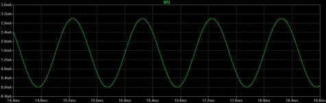
I have downloaded LTSpice and will be experimenting with it. Can you explain what does the SINE (1.5mA 1.5mA 1k) means at the bottom of the screen shot. My guess is 1k sine wave from 1.5mA current source?
This is only the simulation.
The current source represents 1541a, 1.5mA offset, and 1.5mA amplitude sine (1KHz).
Attachments

I would not assume so. You can find quite a few 100mV bias variation with real tubes...
re re 🙂
Well, the schematic for the TDA1541 use an OpAmp to compare the cathode potential with the ground. If the cahode moves, the OpAmp correct as fast as it can the operating point of the tube by acting on its grid. A CRC filter ensures the OpAmp reacts for variations at lesser than 10Hz and does not mix with the mosfet's feedback. After that, I agree OpAmp are not perfects but I can't believe it would let an offset greater than 0,1mV on the cathode.
But I was NOT referring to the coupling cap, but to the Cathode/Source bypass and coupling cap internal to your feedback loop.
Yes me too 🙂
I have seen worse, but you seem to have lot of spuria in these FFT's and you cut the FFT off at 5KHz.
Yes, I wanted to pay more attention to H1 to H5 harmonics. Higher harmonics are melted in the background noise.
Attached one of mine, TDA1541, passive I/V and open loop tube gainstage at 0dbfs, this is without oversampling or other digital filtering, 44.1KHz sample rate.
It can be seen there is "much" 2nd HD (about as much as most speaker drivers produce at 1 Watt input power), but all higher harmonics are < -90dB. The 2nd HD falls quite quickly with lowering level...
That's interesting to see how an open-loop circuit produces high level of H2 whereas high feedback schematic will cancel them and only produce low levels of H3 and H5.
[/QUOTE]
Enjoy !
greg
Hi,
This is what is called a "servo". With Servo's I usually shoot for an 0.1Hz cutoff, not 10Hz and if I can I prefer to use a 2nd order loop.
Servo's can indeed correct the DC operating point, however if they are not very well optimised and implemented I find the worse than a straightforward coupling cap, even an electrolytic one at that.
Yet that is not all a feedback circuit does. In principle an open loop circuit can be made to have lower distortion than what I show (0.01% is not really difficult), I cannot see the point at all. We can design with feedback for as many zeros as we like, yet this says nothing about "good sound"...
Ciao T
Well, the schematic for the TDA1541 use an OpAmp to compare the cathode potential with the ground. If the cahode moves, the OpAmp correct as fast as it can the operating point of the tube by acting on its grid. A CRC filter ensures the OpAmp reacts for variations at lesser than 10Hz
This is what is called a "servo". With Servo's I usually shoot for an 0.1Hz cutoff, not 10Hz and if I can I prefer to use a 2nd order loop.
Servo's can indeed correct the DC operating point, however if they are not very well optimised and implemented I find the worse than a straightforward coupling cap, even an electrolytic one at that.
That's interesting to see how an open-loop circuit produces high level of H2 whereas high feedback schematic will cancel them and only produce low levels of H3 and H5.
Yet that is not all a feedback circuit does. In principle an open loop circuit can be made to have lower distortion than what I show (0.01% is not really difficult), I cannot see the point at all. We can design with feedback for as many zeros as we like, yet this says nothing about "good sound"...
Ciao T
Hi,
The TDA1541 is rated as having a -4mA (peak-peak) output nominal, with digital silence hence at -2mA. The tolerance range is given as 3.4 to 4.6 mA, however in my experience the spread is considerably smaller in reality.
To model the TDA1541 use a -2mA offset and a 2mA peak (1.4mA RMS) AC current source.
Given that my circuit operates the tube essentially with nearly no bias (-0.1V nominal) one must look at 0V Grid curves for a given tube. My data sheets for the 6N30 show around 70mA anode current at 70V and 0V on the grid. I doubt this circuit can work well outside a simulator, with over 5W Anode dissipation per section.
By comparison the 6DJ8/ECC88/6922 has around 16mA at 70V and 0V Grid, which is a bit over 1W per section.
Ciao T
This is only the simulation.
The current source represents 1541a, 1.5mA offset, and 1.5mA amplitude sine (1KHz).
The TDA1541 is rated as having a -4mA (peak-peak) output nominal, with digital silence hence at -2mA. The tolerance range is given as 3.4 to 4.6 mA, however in my experience the spread is considerably smaller in reality.
To model the TDA1541 use a -2mA offset and a 2mA peak (1.4mA RMS) AC current source.
Given that my circuit operates the tube essentially with nearly no bias (-0.1V nominal) one must look at 0V Grid curves for a given tube. My data sheets for the 6N30 show around 70mA anode current at 70V and 0V on the grid. I doubt this circuit can work well outside a simulator, with over 5W Anode dissipation per section.
By comparison the 6DJ8/ECC88/6922 has around 16mA at 70V and 0V Grid, which is a bit over 1W per section.
Ciao T
.................The closest a "2011" might come is a commercial "DIY Module" tube stage I designed a few years back. I would not say that it is worse or better, it is different and was designed to be very compact so it can be fitted as after-market modification to existing CD and DVD Players...
I would post links to this, but as I'm always accused to only post to promote my wares I shall not. Ciao T
Thanks Thorsten, I think you are referring to The Universal Tube Output Stage at The Universal Tube Output Stage-- State-of-the-art Performance Made Easy | Diy HiFi Supply ,well I have posted the link.
Hi,
Could not possibly say, but could be... 😛
Ciao T
Thanks Thorsten, I think you are referring to The Universal Tube Output Stage at The Universal Tube Output Stage-- State-of-the-art Performance Made Easy | Diy HiFi Supply ,well I have posted the link.
Could not possibly say, but could be... 😛
Ciao T
My data sheets for the 6N30 show around 70mA anode current at 70V and 0V on the grid. I doubt this circuit can work well outside a simulator, with over 5W Anode dissipation per section.
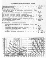
Little overdissipated tube. 🙂
Anode dissipation limit is 4W/sections. Fool-proof safe range up to 80-85%.
English version:
Glass Tube 6N30PDR
Attachments
.............When I remember well in the original Philips datasheet of the TDA1541 there is an indication of the maximum value of the I/V resistor being 27 ohm for distortion reasons.............
Ok! I went through TDA1541A datasheet again and this time managed to find on the end of Page 7, "To ensure no performance losses, permitted output voltage compliance is ±25 mV maximum". Thus the maximum size of resistor becomes 17 Ohm.
Hi,
This is wrong.
First, the Philips Datasheet is conservative. At AMR we did run extensive tests on that. The TDA1541 can handle more but not a LOT more. 50 Ohm I/V resistance is fine.
Secondly, if you want to stay within the 25mV compliance reliably for all possible output currents of the TDA1541 range you need 5.4 Ohm I/V conversion resistor (0.025V / 0.0046mA = 5.435Ohm).
My original "Adagio" DAC with TDA1541 used approximatly this value of resistance and a 1:15 Step Up Transformer. It also used an SRPP output stage tuned for lowest distortion, due to concerns about some of the ultrasonic "images" produced by the absence of oversampling folding back into the audio range.
While sounding good in the end we found the sound better without transformer and with a circuit that did not use agressive cancellation of even order harmonics. This then brings us back to the 2005 TDA1541 Analog stage.
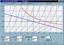
For fun you could try using the E180F triode connected and with the I/V circuit scaled to give you the desired output. For 2V out the I/V resistor becomes 27R and the LCR for the anti-sinc filter scale suitably. The E180F will have lower noise than the 6922 and NOS E180F are not difficult to get and do not quite carry the same silly pricetags as NOS 6922 style tubes.
Based on the Mullard Triode curves the operation will be 75V/12mA, gain is around 50 if CCS or Choke loaded. Output impedance will be around 2.5K.
So the Tango TC-160/15W Choke will be usable as Anode Load choke, otherwise Magnequest may have a suitable item or a CCS (IXYS 10M450 preferred) can be used. It is important to orient the chokes for lowest Hum.
Ciao T
Ok! I went through TDA1541A datasheet again and this time managed to find on the end of Page 7, "To ensure no performance losses, permitted output voltage compliance is ±25 mV maximum". Thus the maximum size of resistor becomes 17 Ohm.
This is wrong.
First, the Philips Datasheet is conservative. At AMR we did run extensive tests on that. The TDA1541 can handle more but not a LOT more. 50 Ohm I/V resistance is fine.
Secondly, if you want to stay within the 25mV compliance reliably for all possible output currents of the TDA1541 range you need 5.4 Ohm I/V conversion resistor (0.025V / 0.0046mA = 5.435Ohm).
My original "Adagio" DAC with TDA1541 used approximatly this value of resistance and a 1:15 Step Up Transformer. It also used an SRPP output stage tuned for lowest distortion, due to concerns about some of the ultrasonic "images" produced by the absence of oversampling folding back into the audio range.
While sounding good in the end we found the sound better without transformer and with a circuit that did not use agressive cancellation of even order harmonics. This then brings us back to the 2005 TDA1541 Analog stage.
For fun you could try using the E180F triode connected and with the I/V circuit scaled to give you the desired output. For 2V out the I/V resistor becomes 27R and the LCR for the anti-sinc filter scale suitably. The E180F will have lower noise than the 6922 and NOS E180F are not difficult to get and do not quite carry the same silly pricetags as NOS 6922 style tubes.
Based on the Mullard Triode curves the operation will be 75V/12mA, gain is around 50 if CCS or Choke loaded. Output impedance will be around 2.5K.
So the Tango TC-160/15W Choke will be usable as Anode Load choke, otherwise Magnequest may have a suitable item or a CCS (IXYS 10M450 preferred) can be used. It is important to orient the chokes for lowest Hum.
Ciao T
Hi,
Given the many configuration options and the options to use current or voltage output there are a lot of ways of doing this.
There is an unpublished article (it was submitted to enjoythemusic.com DIY Mag) that updates my old "Valve analog stages for Digital Audio" article from '99, it has several options that could be adopted...
Ciao T
Hi Thorsten,
Do you have an idea for DAC Output Stage suitable for Sabra ES9018 DAC chip?
Given the many configuration options and the options to use current or voltage output there are a lot of ways of doing this.
There is an unpublished article (it was submitted to enjoythemusic.com DIY Mag) that updates my old "Valve analog stages for Digital Audio" article from '99, it has several options that could be adopted...
Ciao T
Hi,
Given the many configuration options and the options to use current or voltage output there are a lot of ways of doing this.
There is an unpublished article (it was submitted to enjoythemusic.com DIY Mag) that updates my old "Valve analog stages for Digital Audio" article from '99, it has several options that could be adopted...
Ciao T
Might not be a bad idea to post that as a blog if it is going to remain otherwise unpublished? 😀
Hi,
It's kinda long and many need some rework, not very suited to blog. Will see how I do on time.
Ciao T
Might not be a bad idea to post that as a blog if it is going to remain otherwise unpublished? 😀
It's kinda long and many need some rework, not very suited to blog. Will see how I do on time.
Ciao T
Hi,
Given the many configuration options and the options to use current or voltage output there are a lot of ways of doing this.
There is an unpublished article (it was submitted to enjoythemusic.com DIY Mag) that updates my old "Valve analog stages for Digital Audio" article from '99, it has several options that could be adopted...
Ciao T
Thanks.
Any chance for you posting a schematic for Sabra ES9018 in current mode?
Hi,
I have nothing specifically worked out.
Given the outputs can be differential or parralel etc. it is hard to make "one schematic".
In principle just use suitable I/V resistors to Vref of the DAC and a normal tube stage. You will have of Vref worth of offet on the grid, so you need to use suitable cathode biasing.
There is really nothing special to the ESS DAC that does not apply to other DAC Chips.
The Manual for the Universal Tube Stage is on-line, it contains many configurations and also a principle schematic which should be quite clear on the principles. The exact values for parts etc... Well, it's easy enough.
Ciao T
Thanks.
Any chance for you posting a schematic for Sabra ES9018 in current mode?
I have nothing specifically worked out.
Given the outputs can be differential or parralel etc. it is hard to make "one schematic".
In principle just use suitable I/V resistors to Vref of the DAC and a normal tube stage. You will have of Vref worth of offet on the grid, so you need to use suitable cathode biasing.
There is really nothing special to the ESS DAC that does not apply to other DAC Chips.
The Manual for the Universal Tube Stage is on-line, it contains many configurations and also a principle schematic which should be quite clear on the principles. The exact values for parts etc... Well, it's easy enough.
Ciao T
Thanks again.
I'm going to brew differential pair with JFET Cathode CCS fed from a regulated negative supply.
I'm going to brew differential pair with JFET Cathode CCS fed from a regulated negative supply.
Yet that is not all a feedback circuit does. In principle an open loop circuit can be made to have lower distortion than what I show (0.01% is not really difficult), I cannot see the point at all. We can design with feedback for as many zeros as we like, yet this says nothing about "good sound"...
@chanmix51
As is customary when all his technical objections are met ThorstenL attempts to move the focus of an argument to a subjectivist position with no verifiable foundation.
Take heart, however, from the following quote from Douglas Self:
'nods to Subjectivist convention are unlikely to damage real performance; this is however not the case with some of the more damaging hypotheses, such as the claim that negative feedback is inherently harmful'
Hi,
This is wrong...........
...........Secondly, if you want to stay within the 25mV compliance reliably for all possible output currents of the TDA1541 range you need 5.4 Ohm I/V conversion resistor (0.025V / 0.0046mA = 5.435Ohm)...............
....................For 2V out the I/V resistor becomes 27R and the LCR for the anti-sinc filter scale suitably. ............
Ciao T
😱 Sorry all! my fault. Please take my posts with bags of salts (I've written many times that I am beginner).
Thorsten, if it is not too much work, can you or someone else share what will be the new values of LCR filter in this case? Better how do you calculate them? Does this inverse sin(x)/x filter is like parallel RLC filter?
- Status
- Not open for further replies.
- Home
- Amplifiers
- Tubes / Valves
- Thorsten's tube Stage for TDA1541A