Could I replace C7 with the ceramic capacitor?
For the static DC tests we are doing now you can remove C7 altogether.
You have removed C7 ? and the voltage is still high on R9.
What we do next then is build it up piece by piece (not as bad a it sounds) and confirm each and every voltage along the way.
I'll tell you how to do that later... feeding time 🙂
What we do next then is build it up piece by piece (not as bad a it sounds) and confirm each and every voltage along the way.
I'll tell you how to do that later... feeding time 🙂
OK.
So let me be sure what you are saying. When C7 was fitted the voltage on R9 was high and now with C7 removed it falls around 1.26 volts. If that is what you mean then C7 is definitely faulty.
So let me be sure what you are saying. When C7 was fitted the voltage on R9 was high and now with C7 removed it falls around 1.26 volts. If that is what you mean then C7 is definitely faulty.
yes, it was like you describe it. I could't fit C7 back to check as I've destroyed it.
But now itss only 1.26v on R9 and T1 and T3 are fitted in place. C7 and T5 removed
But now itss only 1.26v on R9 and T1 and T3 are fitted in place. C7 and T5 removed
with T3 + T1 it was 45V and with only T1 (T3 off) it was unstable 4-7V.
But now T1+T3 give me stable 1.26v
But now T1+T3 give me stable 1.26v
That's good then, it sounds like C7 really was faulty. Now whether anything else is faulty remains to be seen.
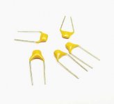
Do you have any small caps like the 100pf C7 ? Its value isn't super critical and I would think anything around 68pf to perhaps 470pf would work OK. We could see how it all works without even fitting C7 if you haven't got one.
For testing the whole circuit and to see whether it all works or not requires everything connecting back up again, T5, and the motor.

Everything is back but I have no capacitors so powerd up it without C7...
Motor Rotates!!!😀😀😀😀 It's working!!!
Have only some problems with the 16 speed as the voltage jumping up and down. Could it be due to no C7 on the PCB? Will try to rotate the potentiometers to give it 2.5V at that speed.
Motor Rotates!!!😀😀😀😀 It's working!!!
Have only some problems with the 16 speed as the voltage jumping up and down. Could it be due to no C7 on the PCB? Will try to rotate the potentiometers to give it 2.5V at that speed.
Oh my God! I power it on again and it's not working like it was! I's 0,6V AC going to the motor and 32V DC on the R9. WTF?
The joys of faultfinding 😀
At least we seem to have found the problem with C7.
You are going to have to fit a new cap and then we can take it from there. Its a bit hard to analyse the circuit fully because the motor characteristics will play a big part in how it behaves dynamically.
At least we seem to have found the problem with C7.
You are going to have to fit a new cap and then we can take it from there. Its a bit hard to analyse the circuit fully because the motor characteristics will play a big part in how it behaves dynamically.
New C7 fitted. Now I have new sympthoms:
It could work perfectly and stable for a minute (there is 5V AC to the motor on 33 spped and it spins like it should be) but then suddenly something happens and the motor begin to wobble it could stop and going the wrong directon then stop and wobble back and forth and so on. On the pcb at this moment Bulb begins to blink and there is a voltage drop to the motor. It jumping 4-5V AC while it should be stable 5V. On the 16 speed everything is more bad. And there is some strange noise in the motor. On the 45 it's better but there is defenetly something on the PCB is faulty.
The DC voltage on C9 when everything is connected now is 22-30V and it's jumping!
Is the new cap definitely 100pf ?
Has the board got any previous unknown history ? Is it possible the preset resistors R17 and R22 have been altered in the past ?
Its unusual to find a definite fault (C7) and yet still find the unit isn't OK after replacing it. Have C2 and C3 been replaced ?
Has the board got any previous unknown history ? Is it possible the preset resistors R17 and R22 have been altered in the past ?
Its unusual to find a definite fault (C7) and yet still find the unit isn't OK after replacing it. Have C2 and C3 been replaced ?
- Status
- Not open for further replies.
- Home
- Source & Line
- Analogue Source
- Thorens 125 MK1. Help me please repair this PCB.