T3 emitter - 45V
T3 base - 45V
T3 collector - 45V
That means either T3 or T1 (or both, one could have damaged the other) is faulty.
Do you have any small transistors you can use ?
(in those diagrams I had the supply at 34 volts.... but its nearer 45. It doesn't affect the relationship of the voltages shown, just the absolute levels)
R10 should be at the supply voltage, that's OK.
R9 should not and that means that voltage is coming from either T1, T3 or T6. That doesn't mean they are all faulty, but there is a good chance at least one of them is.
Try this. If you now remove T1 and T3 then there is no route for the supply voltage to reach R9 and the voltage on R9 should fall. Does it ?
Yes I have a transistors
Are they direct replacements ? I think its worth you changing them if you can.
The problem with direct coupled stages like this is that a fault in one section can damage other parts.
Do I need to remove both T1 and T3 now?
Yes, try that first. Lets see if we can make some sense from all this. With those removed the voltage on R9 should fall. Lets at least make sure that happens.
Now I have 49V to R10 and 2.5-4V to R9. It's very unstable and the bulb is blinkikg
That sounds reasonable actually. The bulb and oscillator wont work correctly with the transistors removed but its not that we are testing here.
It looks like there is definitely a problem around those two removed transistors.
Refitting just T1 shouldn't change what you are seeing now. So I would do that... and use one of your replacements. Don't fit T3 just yet. Recheck the volts on R9 first and if its still OK (low) then fit a replacement for T3. Now test R9 voltage again. It still should be low. If it is then we can think about trying it all out again.
One step at a time 🙂
I've to go out so it will be a few hours before I look in again.
T1 is BC171B. Could I use BC147A or BA147B instead of it?
Yes, but make sure you get the pin outs correct.
T1 replaced with the BC147B. Voltage on R9 is 4-7V.
I think we have to accept that as OK as long as you are 100% sure T1 is good and fitted correctly. It isn't as low as I would have thought given that the motor is disconnected.
Refitted T3 and it's 45V on the R9 again!
And this result is with T5 still out of circuit. If so then T3 is definitely faulty and/or C7 is breaking down under voltage and turning T3 on.
With T5 removed, fitting T3 should make no difference to the voltage on R9.
Something is happening around there 🙂
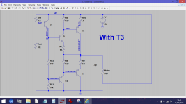
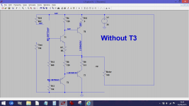
With T5 removed all we have is R19 (8k2) across the base/emitter junction of T3. That means T3 is off, it is non conducting. So the voltage you see on R9 should be the same whether T3 is fitted or not.
The working simulation confirms that would be the case to.
With T5 removed all we have is R19 (8k2) across the base/emitter junction of T3. That means T3 is off, it is non conducting. So the voltage you see on R9 should be the same whether T3 is fitted or not.
The working simulation confirms that would be the case to.
Attachments
- Status
- Not open for further replies.
- Home
- Source & Line
- Analogue Source
- Thorens 125 MK1. Help me please repair this PCB.