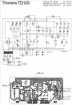
But wash the boards first before ordering new ones..
I think this too and just concentrate on the one board.
You have to work on the definite observed fault that we have, which is high voltage on isolated print. Forget what is happening elsewhere on the board or what happens when its assembled. Work on the one definite thing we know... that there should be no voltage on your isolated print.
Hi,
I have been followed this thread and I like to give some advices also. I had some experienced while troubleshoot some amplifiers boards with the same problem experiencing here. Found that the board had some bridged between copper run due to when the board was etched with the acid solution didn't eat clean the copper between run. The way I fixed was by taking an Exacto knives and cut the board around the copper run. That fixed the problems on the boards. Also I used acetone to clean the board from the acid flux used in the solder. After cleaned the board with acetone used a magnified glass to check the board for solder bridged between connections. Sometime it is hard to see if you have a bridge between connections. Hoped these suggestions will help keep troubleshoot the problem.
I have been followed this thread and I like to give some advices also. I had some experienced while troubleshoot some amplifiers boards with the same problem experiencing here. Found that the board had some bridged between copper run due to when the board was etched with the acid solution didn't eat clean the copper between run. The way I fixed was by taking an Exacto knives and cut the board around the copper run. That fixed the problems on the boards. Also I used acetone to clean the board from the acid flux used in the solder. After cleaned the board with acetone used a magnified glass to check the board for solder bridged between connections. Sometime it is hard to see if you have a bridge between connections. Hoped these suggestions will help keep troubleshoot the problem.
There is no need for multi-turn controls. Just because they are multi-turn does not increase the quality. If anything, good quality 10 turn controls would cost a lot more than the single turn ones. If you have to replace the trimmer controls, use cermet types from a reputable manufacturer. Those original controls were not the least expensive ones you know.
The switch contacts are heavily plated. I hope the original boards can be saved. The tables look like they are well worth saving. If I found one in this condition, I would do everything suggested in this thread to save them. That includes the deep clean and bake out. Consider that these will run for years afterwards if they can be repaired.
-Chris
kudos for the patience and determination of all involved here.
For some reason scenes from the movie Airplane keep coming to mind!
For some reason scenes from the movie Airplane keep coming to mind!
PCB exchange
I'm back again🙂
Dear gurus, I have a working PCB of the thorens 125 MKII turntable and a working motor of the MKI. PCBs as well as the motors of mk1 and mk2 are not the same. But is it possible to modify PCB of the MK2 to work well with the mk1 motor?
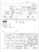
Here the photos of the both PCBs.


Defference in the motors
MK1 seem to be a 12V version motor
Coils resistance is
11.8Ohm red-black
9.3Ohm blue-black
MK2 seem to is a 16V version motor
Coils resistance is
29Ohm red-black
27.3Ohm blue-black
Here the difference in the trimpots to correct the speeds:
Connect meter (dmm) to test points ge and rt (phase 1) and adjust:
45rpm set R10 for 6V (R18 for 8V on the MK1)
33rpm set R9 for 5V (R16 for 5V on the MK1)
16rpm set R8 for 3.2V (R15 for 2.5V on the MK1)
connect meter to test points ge and bl (phase 2) and adjust:
45rpm set R13 for 6V (no pahse 2 ont the mk1 pcb)
33rpm set R12 for 5V (no pahse 2 ont the mk1 pcb)
16rpm set R11 for 3.2V (no pahse 2 ont the mk1 pcb)
Speed adjust:
set pitch control to centre position and adjust:
45rpm set R18 for stationary display on strobe ring (on the mk1 R29)
33rpm set R20 for stationary display on strobe ring (on the mk1 R28)
16rpm set R22 for stationary display on strobe ring (on the mk1 R27)
What could I do on the PCB mk2 to make a correct work with the mk1 motor?
I'm back again🙂
Dear gurus, I have a working PCB of the thorens 125 MKII turntable and a working motor of the MKI. PCBs as well as the motors of mk1 and mk2 are not the same. But is it possible to modify PCB of the MK2 to work well with the mk1 motor?
Here the photos of the both PCBs.


Defference in the motors
MK1 seem to be a 12V version motor
Coils resistance is
11.8Ohm red-black
9.3Ohm blue-black
MK2 seem to is a 16V version motor
Coils resistance is
29Ohm red-black
27.3Ohm blue-black
Here the difference in the trimpots to correct the speeds:
Connect meter (dmm) to test points ge and rt (phase 1) and adjust:
45rpm set R10 for 6V (R18 for 8V on the MK1)
33rpm set R9 for 5V (R16 for 5V on the MK1)
16rpm set R8 for 3.2V (R15 for 2.5V on the MK1)
connect meter to test points ge and bl (phase 2) and adjust:
45rpm set R13 for 6V (no pahse 2 ont the mk1 pcb)
33rpm set R12 for 5V (no pahse 2 ont the mk1 pcb)
16rpm set R11 for 3.2V (no pahse 2 ont the mk1 pcb)
Speed adjust:
set pitch control to centre position and adjust:
45rpm set R18 for stationary display on strobe ring (on the mk1 R29)
33rpm set R20 for stationary display on strobe ring (on the mk1 R28)
16rpm set R22 for stationary display on strobe ring (on the mk1 R27)
What could I do on the PCB mk2 to make a correct work with the mk1 motor?
All this was many thousands of posts back in time for me...... and without re-reading it all I can't remember a lot of the detail and what test you gear you had. I think you had a scope though ?
The second board seems to drive the motor from a bridged amplifier.
First question. What is the original motor doing when wired to the new board ? Is it rotating ?
Without seeing one for real I can only guess at things to suggest. You could try driving the motor from just the right hand amplifier and connecting the Rt lead via a cap to the positive rail (as in the other board).
Ultimately it may not be possible without a lot of research and work.
You need to see what the amplitude of the drive signal is from each board. Are they similar ?
Mooly, may be I was need to start a new thread with my last post?
I don't really want to restore the faulty pcb MK1 that is not woking and seem to be conducting. The new idea to modify pcb of the mk2 that has a different layout.
I will check everything you will ask me! A also have an oscilloscope and could use it too!
I don't really want to restore the faulty pcb MK1 that is not woking and seem to be conducting. The new idea to modify pcb of the mk2 that has a different layout.
I will check everything you will ask me! A also have an oscilloscope and could use it too!
What should I measure so you could understand if it's a hard work or not? Should I give you the photos from my oscilloscope of both pcbs?
OK.
You need to be prepared to a lot of experimentation to see what will work. The second board version seems to be a much lower current version with much smaller power transistors. That means you might have to be prepared to replace those with something bigger (TIP41/TIP42 might be a possible) and then see just how much current and voltage the original motor needs.
You need to be prepared to a lot of experimentation to see what will work. The second board version seems to be a much lower current version with much smaller power transistors. That means you might have to be prepared to replace those with something bigger (TIP41/TIP42 might be a possible) and then see just how much current and voltage the original motor needs.
What should I measure so you could understand if it's a hard work or not? Should I give you the photos from my oscilloscope of both pcbs?
Its more a case of experimenting to get a feel for what is going on.
For example, we need to be seeing either a similar drive voltage to the motor from the later board if we are to attempt to couple the original motor in a similar way to the first board or around half the voltage if we were to use the bridge configuration and couple it as per the second version.
Yes, you could do that but remember its AC and so you might need to calculate it by measuring the volt drop (on a scope) across the 0.3 ohms in the original, and by adding a known low value resistor into the second.
The original seems to rely on three different value electrolytics to couple the motor to the supply and that could indicate they are needed to get a different phase shift (voltage vs current) for each frequency (speed).
You may not be able to get that motor to run satisfactorily on the second version... but its trial and error and experimentation to see what if anything works.
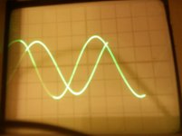
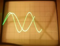
Measurement was done on the 33rpm where was the same 5v voltage on the pots.
So on the working decks amplitudes are the same but the frequencies are different!
So on the working decks amplitudes are the same but the frequencies are different!
The height is the voltage amplitude. So both are similar.
The width is the frequency, so the wider one is running at a slower speed.
Because the amplitudes are similar, I think the first thing is to try and couple the MK1 motor in a similar way to the original MK1 board which means connecting it via a suitable value electrolytic cap to the positive rail. Then see if it spins up OK.
Disclaimer 😉 you are going to have to decide whether the MK2 board can deliver the current required with those smaller transistors. So be careful and take it slowly. No guarantees with any of this and you are going to have to do a lot of experimenting yourself to see what works and what does not.
Now I've connected Mk1 motor to the Mk2 pcb. It's working! Also it's rotating if I disconnect red or blue wire to it+
What should I do next?
Those smaller transistors on the mk2 are often broken with the native motor so with the mk1 I think they will fail faster! The problem is only with this transistors? Could we replae them with something more powerful?
Those smaller transistors on the mk2 are often broken with the native motor so with the mk1 I think they will fail faster! The problem is only with this transistors? Could we replae them with something more powerful?
Should I just add a capacitor between the pot of the red wire of the PCB and the red pot of the motir? What capacitance should I add? How to connect it?
Now I've connected Mk1 motor to the Mk2 pcb. It's working! Also it's rotating if I disconnect red or blue wire to it+
Slow down 🙂 your running ahead to fast.
Does the MK1 motor and MK1 board also run if you disconnect the red or blue wire ?
It would seem to be a good idea to replace those transistors. Perhaps BD131 and BD132 would be a good choice (and fitted with small heatsinks).
Also, do you also understand 🙂 that I haven't got all the answers to this. Suggesting things to try at the end of a keyboard is totally different to working on one for real. So you are going to have to try things for yourself.
- Status
- Not open for further replies.
- Home
- Source & Line
- Analogue Source
- Thorens 125 MK1. Help me please repair this PCB.


