I've found some info on adjusting the turntable on http://www.lencoheaven.net/forum/index.php?topic=14066.0
Perhaps the values given in the thread provide some extra information to isolate the cause of the problems...
Perhaps the values given in the thread provide some extra information to isolate the cause of the problems...
Last edited:
Thank you esgigt but the info there is the first I do with the boards.
Mooly! I've put back C7 resistor make the last attemt to isolate this zone and now I have 0V there and across the base/emitter of T1 and that was with T1 and T3 is also 0V! What is next to check/do?
Mooly! I've put back C7 resistor make the last attemt to isolate this zone and now I have 0V there and across the base/emitter of T1 and that was with T1 and T3 is also 0V! What is next to check/do?
I am following this thread from the beginning.
Conducting PCB boards do happen, but only in bad layed out high voltage circuits (tubes) or in extremely high impedance circuits.
This is a simple, forgiving old school circuit and PCB board, really not rocket science.
Something basic has to be wrong, and we are running around in circles.
I know, faults in simple circuits can sometimes be very hard to track...
Mooly! I've put back C7 resistor make the last attemt to isolate this zone and now I have 0V there and across the base/emitter of T1 and that was with T1 and T3 is also 0V! What is next to check/do?
Last attempt 🙂
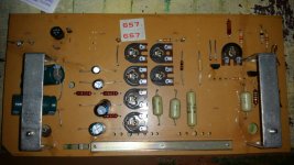
You make the board look like this. T6 base and T7 base are isolated. T3 is removed. R14 which is a 15k is removed. T1 and T2 are fitted.
You should have zero volts between ground and R9. Ground is C3 negative.
Attachments

Hi 968driver,
Mooly is well aware of this and is trying to focus terrom onto one ordered track of investigation. There does appear to be either something wrong with the PCB material or contamination at this point in time. What is important right now is to keep everyone on the same track.
Hi Mooly, terrom,
Sorry to barge in like this. There is one thing that might help right now if it is a board contamination issue. Terrom, please do not do anything right now and listen to Mooly while I outline this procedure. Its vital that you stay in step with Mooly.
Remove the Transistors, capacitors and trimmer controls from the PC board. Take pictures that show the position of each part first, and measure each control and carefully place it in order. They must be installed in the exact same place with the same settings.
Send the PCB through the dish washing machine as you would with dishes (same soap). After that, place in an oven set low to perhaps 180 F°, or the Celsius equivalent for a couple hours. Allow to air dry. You can now measure each resistor to make certain it is at the correct value. Measure the resistance between traces as well. Then reinstall all the parts you removed earlier and connect the PCB back to everything but the motor. Your setup will now be at the same place it was when you started the cleaning procedure.
It is critical that you wait for Mooly to tell you if he wants you to do this. Please don't do anything until Mooly asks you to, and do not do anything else past that. Step by step is the only way you will get anywhere.
-Chris
I have never, ever experienced a conducting PCB board in low voltage applications.
These boards have a green solder mask, this makes it very difficult to draw conclusions from fotographs.
Measurements seem to be doubtfull and inconclusive.
Mooly has angelic patience, and this could well be the only way to solve this problem. Respect!
These boards have a green solder mask, this makes it very difficult to draw conclusions from fotographs.
Measurements seem to be doubtfull and inconclusive.
Mooly has angelic patience, and this could well be the only way to solve this problem. Respect!
Hi Mooly, terrom,
Sorry to barge in like this.
-Chris
🙂 No problem. The more ideas and the better. To get to the point where we are now, and where it really does seem to look as though the board itself is the suspect has been a long journey. Depopulating the board and giving it a major clean and dry off might well be one avenue to explore.
I notice again that terrom has refitted C7 and again, the 'ghost' voltage has fallen to zero.
A few days ago (before we started major testing) C7 was replaced and the board worked for a little while. The common denominator is heat being applied to that area.
I have never, ever experienced a conducting PCB board in low voltage applications.
These boards have a green solder mask, this makes it very difficult to draw conclusions from fotographs.
Measurements seem to be doubtfull and inconclusive.
Mooly has angelic patience, and this could well be the only way to solve this problem. Respect!
Thanks 🙂 Most (all) conducting boards I've come across usually had a four legged furry friend as the start of it all.
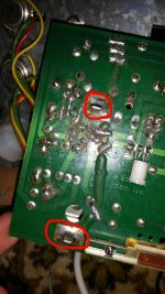
This second 2bridge board seem to be conductive as I couldn't explain that small isolated zone mesures a voltage from 1 to 10V. Same for the isolated part that is a fixing stand for the pcb. What other explanations could be?
Other thing is that electolitycs capacitors on it were very dry abd cracked. It's seem to be that the storage wasn't good. So may be this pcb become conductive?
On the first 1 bridge version pcb i don't belive in conductive. It's in good clean condition but was cracked. Seem to be that something is shorted but I'm in dead end with it too=(
Hi terrom,
Then clean both, but one after the other so you keep them completely separate. Take pictures and write down measurements. Keep all these apart from the other. Above all, do not do anything unless Mooly says to, then only what he says.
Mooly is doing everything exactly right. That's why I am hanging back.
Hi Mooly,
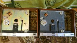
Come to think of it, what do those two turntables actually look like now? I'm not sure I want to look!
-Chris 🙂
Then clean both, but one after the other so you keep them completely separate. Take pictures and write down measurements. Keep all these apart from the other. Above all, do not do anything unless Mooly says to, then only what he says.
Mooly is doing everything exactly right. That's why I am hanging back.
Hi Mooly,
But ... but ... it's a TURNTABLE! What a horrible mental picture!Most (all) conducting boards I've come across usually had a four legged furry friend as the start of it all.
Come to think of it, what do those two turntables actually look like now? I'm not sure I want to look!
-Chris 🙂
Does anybody know if I could use pcb from the Thorens 125 MKII version. I know that it's a little different and operates with the motor that need 3,2V, 5V and 6V AC. MK1 motor needs 2,5V, 5V, 8V for each speed. But I could rotated potentiometers on the MK2 pcb so it also will give 2,5V, 5V, 8V AC that is need for a MK1 motor. Is there any other problems?
Hi terrom,
What you are suggesting makes no sense for starters. You have two different PCBs with different problems. You set frequency and speed on the driver boards, and you require your oscilloscope to set the voltages. You would be throwing everything into a confused mess. If you are really considering this, save the turntables by giving them to someone who has a lot more experience in servicing electronics.
One thing I am very curious about is what the rest of these turntables look like - what condition are they in? If I lived across the pond, I would try to get one of those for myself as a backup to my TD-125 MKII.
I am quite serious about what you should do if you have decided to abandon the help Mooly was giving you. Right now you are at the edge of either getting one or both working if you follow the advice, or knowing they are not repairable for certain. Giving up now after all the work both you and Mooly have put in is such a shame.
-Chris
This second 2bridge board seem to be conductive as I couldn't explain that small isolated zone mesures a voltage from 1 to 10V. Same for the isolated part that is a fixing stand for the pcb. What other explanations could be?
From all the evidence we have up to this point, there can not really be another explanation. To see any significant voltage on any isolated area of board means there has to be leakage and remember you are measuring voltages as high as 10 volts here. That is not just a stray reading or stray pickup from a floating meter lead. To see even 1 volt dc is 'real'.
Our options are limited. If any contamination has soaked into the board then I doubt you will ever get a satisfactory result. There will always be doubt and the possibility of problems returning... maybe something that attracts moisture (a bit like salt does) has got into the board.
There are really only two options left. Wash the board as it stands and low bake below 60 to 70C for a couple of hours and then retest to see if there has been any improvement in the leakage. The other option is to do as anatech suggests and go all out removing all parts and then wash and high(er) temperature bake the boards. In that case you would not need to rebuild it all to see if it was successful. It would need only the power supply parts and R6 and T1 fitting to see if the voltage on the isolated bits of print was still there.
it's seem to be the first pcb also conducting.
The fixing metal part that is isolated to any trace has 21V in it. The same part on the ridgt has a zero voltage. Also when I screw the pcb to it's place on the turntable the whole turntable has 21V! It's because of this part touches it.
The fixing metal part that is isolated to any trace has 21V in it. The same part on the ridgt has a zero voltage. Also when I screw the pcb to it's place on the turntable the whole turntable has 21V! It's because of this part touches it.
Attachments
Last edited:
Have you considered having new PCBs made ? Not a particularly cheap option but the design is very simple and would be easy to copy.
Yes I want it very much. How much could it cost? Who should make a design for the company wich will produce this board? May be I could pay someone here who could make a dezine of such a pcb?
Yes I want it very much. How much could it cost? Who should make a design for the company wich will produce this board? May be I could pay someone here who could make a dezine of such a pcb?
I know there are companies in Asia who make PCB's at low cost and at a reasonable quality... Then you can also exchange the old pots for more reliable (multi-turn?) new ones..
But wash the boards first before ordering new ones..
- Status
- Not open for further replies.
- Home
- Source & Line
- Analogue Source
- Thorens 125 MK1. Help me please repair this PCB.