If the transistors are hot driving the new motor then you should replace then with something a little higher powered and fit heatsinks (as we mentioned earlier).
The power supply shouldn't be very critical for this. Just replace any old electrolytics with new but I would suggest you get it all working first. The more things you change, the harder it is to sort out problems.
The power supply shouldn't be very critical for this. Just replace any old electrolytics with new but I would suggest you get it all working first. The more things you change, the harder it is to sort out problems.
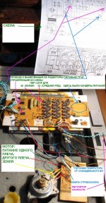
I fit mk1 motor to the mk2 pcb. 45 speed setting. voltage of phase1 set to 5V. voltage of phase2 set to 4V. At that way amplitudes on the scope are almost the same. Motor at such sets is rotating only a few second but then stops.
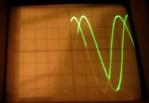
While it rotates well on the 33 speed at default position for the mk2 motor at 5volts for the 33 speed.
Also interesting for me that 1st potentiometer is changing the amplitude of the both sinewaves while the second is only for the one of the two.
What is wrong now?

While it rotates well on the 33 speed at default position for the mk2 motor at 5volts for the 33 speed.
Also interesting for me that 1st potentiometer is changing the amplitude of the both sinewaves while the second is only for the one of the two.
What is wrong now?
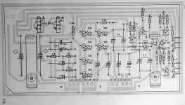
The amplitude presets work in pairs. Presets 8, 9 and 10 set the amplitude of the first amplifier output for the three respective speeds.
So the diagram shows speed control R20 as being selected. Preset R9 sets the amplitude of the output from the first amplifier, that's on T3 and T4. Preset R12 will then be used to set the amplitude of amplifier two so that it matches that of the first one.
I don't know why its not running on 45 rpm. Perhaps the internal characteristics of the motor are different.
Why not try coupling the motor as we talked about yesterday. Try disconnecting the wire to the motor that goes to the second bridge amp, and instead connect it via a cap to the positive rail... just like in the Mk1 board. Use a similar value cap as the Mk1, so that would be 100uf for 33rpm and 75uf for 45rpm. Perhaps the Mk1 motor relies on the phase shift the cap will introduce.
You will have to try it and see what happens. You might need to turn the amplitude of the drive voltage up to get it to rotate correctly.
Try it... see if it works.
Hi terrom,
Is it possible your 'scope channels are out of cal, or you have a bad lead? Set both amplitudes to the same voltage on your meter, or using the same channel on your oscilloscope (set to DC coupling for these low frequencies).
Sometimes the motor must be turning the platter in order to keep running. But as I said earlier, you have to set the MKII board to what the motor "sees" when driven by it's MKI board. The entire idea is that the motor shouldn't know what it is being driven by. If you make the MKII board deliver the same amplitudes and frequencies of the MKI board, the motor will run properly as long as it isn't defective.
So, set the drive voltages up as you would for the MKI board, same for the frequencies. Ignore the calibration section for the MKII board except for the pots to adjust and the connections to make.
As Karl mentioned earlier, if the motor is driven with a bridge type driver stage, set each side for 1/2 of what the measurement states in the MKI manual. To make it clear, measure across the motor and set it up for the voltage mentioned in the MKI manual with your meter. Ignore the fact that there is a common ground point. With bridged drive (both sides hot), you cannot connect the wires that used to go to "common" together or you will short 1/2 of each driver amplifier. Smoke normally follows an attempt to do this.
-Chris
Say what?voltage of phase1 set to 5V. voltage of phase2 set to 4V. At that way amplitudes on the scope are almost the same.
Is it possible your 'scope channels are out of cal, or you have a bad lead? Set both amplitudes to the same voltage on your meter, or using the same channel on your oscilloscope (set to DC coupling for these low frequencies).
Sometimes the motor must be turning the platter in order to keep running. But as I said earlier, you have to set the MKII board to what the motor "sees" when driven by it's MKI board. The entire idea is that the motor shouldn't know what it is being driven by. If you make the MKII board deliver the same amplitudes and frequencies of the MKI board, the motor will run properly as long as it isn't defective.
So, set the drive voltages up as you would for the MKI board, same for the frequencies. Ignore the calibration section for the MKII board except for the pots to adjust and the connections to make.
As Karl mentioned earlier, if the motor is driven with a bridge type driver stage, set each side for 1/2 of what the measurement states in the MKI manual. To make it clear, measure across the motor and set it up for the voltage mentioned in the MKI manual with your meter. Ignore the fact that there is a common ground point. With bridged drive (both sides hot), you cannot connect the wires that used to go to "common" together or you will short 1/2 of each driver amplifier. Smoke normally follows an attempt to do this.
-Chris
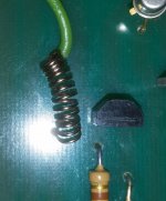
Looks to be resistance wire. Cheap way I suppose to make a non standard (in size or in value) resistor.
Hi terrom,
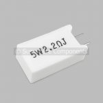
That is a high power wirewound resistor. The wire is special resistance wire and looks fine. It can be replaced approximately with wirewound resistors if need be, but I would leave that in place.
-Chris
That is a high power wirewound resistor. The wire is special resistance wire and looks fine. It can be replaced approximately with wirewound resistors if need be, but I would leave that in place.
-Chris
There is no need at all to replace this resistor. It is made for eternity, cannot go wrong.
First rule: keep as much as possible everything on the PCB original.
You have to localize the component(s) that is/are causing the trouble.
Randomly replacing components will get you nowhere.
This is a relative simple analog circuit, however, some experience and knowledge of basic electronics is a must.
I have the impression you are overlooking something obvious.
Best regards,968driver.
Hi terrom,
Yes, leave it alone. The original can take huge surge currents which a metal film will not. Why the devil are you even thinking about replacing the resistor? Even the inductance is probably designed in. I wouldn't take changing that part lightly.
-Chris
Yes, leave it alone. The original can take huge surge currents which a metal film will not. Why the devil are you even thinking about replacing the resistor? Even the inductance is probably designed in. I wouldn't take changing that part lightly.
-Chris
I want to build the pcb with the new components but it's not possible to find such a spring resistor! 0.3ohm is very rare!
Hi terrom,
Okay, you can get some resistance wire and create your own, or use a 0R27 or 0R33 resistor, but it must be wirewound! Film - anything is no good for this.
-Chris
Okay, you can get some resistance wire and create your own, or use a 0R27 or 0R33 resistor, but it must be wirewound! Film - anything is no good for this.
-Chris
I cann't find wirewound resistors anywhere! It's only 0.3Ohm (or 0.27 or 0.33too). Who could sell them?
You say that this wirewound resistor can take huge surge currents. This is the reason why they use it here? It's not possible to use film here at any wattage?
Mooly say that "As long as the wattage is sufficient then it would be fine but there is really no need". It'😱s not correct?
You say that this wirewound resistor can take huge surge currents. This is the reason why they use it here? It's not possible to use film here at any wattage?
Mooly say that "As long as the wattage is sufficient then it would be fine but there is really no need". It'😱s not correct?
- Status
- Not open for further replies.
- Home
- Source & Line
- Analogue Source
- Thorens 125 MK1. Help me please repair this PCB.
