And look on the left side there is a mark "0V" but I have 6V (but with the T5 removed if this make any sense).
That board doesn't match the one here,
http://www.diyaudio.com/forums/anal...k1-help-me-please-repair-pcb.html#post4379431
The oscillator has been modified greatly but the transistor layout is similar.
Answer these carefully.
1/ Does that '0V' marking and that print go to T5 base ? Yes or no !
2/ If the answer was 'yes', then are you saying you have 5 volts on the print where it says '0V'. Yes or no !
3/ If 'yes' then is that with T5 removed. Yes or no !
With T5 removed, clean the board carefully around the transistor pads. Leakage from collector to base on the board would cause this.
4/ Is the soldered break in the board OK and bridged with wire. It looks fractured in the picture... maybe its OK and its just the photo makes it look like that.
I'm noot a fool. Belive me please!
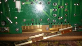
There no connections to the T5 base. Only from the resistor and the switch.
1. YES
2. YES. 6V or even more
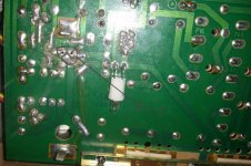
3. YEEEES! No transostor. Here the photo.
Everything cleaned. No connections to cllector. I see 2mm space between each pot.
4. There is no break. It's full of solder and there is wire inside it. And I cheked continuity by the DVM. It's OK.
There no connections to the T5 base. Only from the resistor and the switch.
1. YES
2. YES. 6V or even more
3. YEEEES! No transostor. Here the photo.
Everything cleaned. No connections to cllector. I see 2mm space between each pot.
4. There is no break. It's full of solder and there is wire inside it. And I cheked continuity by the DVM. It's OK.
Attachments
I'm noot a fool. Belive me please!
There no connections to the T5 base. Only from the resistor and the switch.
1. YES
2. YES. 6V or even more
3. YEEEES! No transostor. Here the photo.
Everything cleaned. No connections to cllector. I see 2mm space between each pot.
4. There is no break. It's full of solder and there is wire inside it. And I cheked continuity by the DVM. It's OK.
I do believe you... remember you have the huge advantage of having the board in your hand, I don't.
You can do this...
So the transistor is removed
 and we still have voltage on that print.
What you must do then is look at every single connection and part that connects to that print and isolate them all methodically. In the end you will be left with a piece of print with nothing attached and no voltage present.
I'm going to do a drawing to show you what you have at this stage.
So when the switch is dismantled, you are saying the voltage on T5 base disappears ?
Yes or no 🙂
Yes or no 🙂
OK.
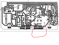
Now tell me which board layout we are working on. Is it the one in post #262 or the one at the beginning in post #6 ?
Now tell me which board layout we are working on. Is it the one in post #262 or the one at the beginning in post #6 ?
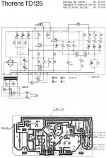
Yes. Everything is near 0v.OK. So this is the early 'simple' board.
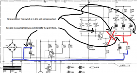
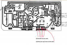
Check that there is NO voltage on all 6 points shown here and confirm again (just to make sure the fault is consistent 🙂) that there is still no voltage on the print to T5
Отправлено с моего SM-G900FD через Tapatalk
OK. That's good by the way.
So this is a very strange situation where it seems as though the switch itself is somehow putting voltage on this point.
What we do next...
1/ Visually check the switch looks OK. Check that there are no shorts between the spring switch contact and the metal bar that holds it all.
Use your meter on a 'high ohms range' (that's a range that would measure 1meg or 10meg resistors) to measure between the moving switch contact and the metal bar holding it. There should be infinity.
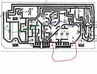
2/ If the switch looks OK then I think we should build the circuit up again by refitting T5 and anything else that has been removed or disconnected but still leave the switch out at this point
3/ We now link the other parts of the switch out with wire and see what happens when its powered up.
I'll post you a diagram of that in a minute.
So this is a very strange situation where it seems as though the switch itself is somehow putting voltage on this point.
What we do next...
1/ Visually check the switch looks OK. Check that there are no shorts between the spring switch contact and the metal bar that holds it all.
Use your meter on a 'high ohms range' (that's a range that would measure 1meg or 10meg resistors) to measure between the moving switch contact and the metal bar holding it. There should be infinity.
2/ If the switch looks OK then I think we should build the circuit up again by refitting T5 and anything else that has been removed or disconnected but still leave the switch out at this point
3/ We now link the other parts of the switch out with wire and see what happens when its powered up.
I'll post you a diagram of that in a minute.
Switch slider is OK. I tried another one from the other turntable.
There is no connection between the spring switch contact and the metal bar that holds it all.
There is no connection between the spring switch contact and the metal bar that holds it all.
Stick to the plan.
You have conclusively proved by measurement that the mysterious voltage on T5 print appears when the switch is in place, and vanishes when the switch is removed.
That's fact... you have measured and observed that happening.
You have also proved by measuring that the voltage is still missing when the switch is linked out with wire. Yes 🙂
So we carry on with the plan.
- Status
- Not open for further replies.
- Home
- Source & Line
- Analogue Source
- Thorens 125 MK1. Help me please repair this PCB.