OK.
Now we do this second board (the two bridge one) slowly and methodically. All these tests are done with the motor disconnected.
The very first check is to make sure the plus and minus 22 volt rails are correct. Now you said the other day that the voltages only appeared when T6/T7 and R10 and R6 were removed. Lets confirm that and see why.
-----------------------------------------------------------------------------------------------------
Just work thorough these tests carefully, and we begin with the board all assembled and all parts fitted. Connect your meter black lead to C3 negative.
1/ What is the voltage on C3 positive lead ?
2/ What is the voltage on C2 negative lead ?
If the voltage is lower than around +20 volts for C3 and -20 volts for C2 then do the next steps.
3/ Disconnect R10 and R9 and recheck the voltages.
Has the voltage now come back to the correct level ?
That is enough for the first step.
Ok. Should I first solder all the components? AD149 base, Resistors r10 r6?
and we begin with the board all assembled and all parts fitted.
Yes 🙂
It's very strange with the motor fitted:
1/ What is the voltage on C3 positive lead ? 12.2V
2/ What is the voltage on C2 negative lead ? minus 21.66V
without the motor
1/ What is the voltage on C3 positive lead ? 23.6V
2/ What is the voltage on C2 negative lead ? minus 24.66
1/ What is the voltage on C3 positive lead ? 12.2V
2/ What is the voltage on C2 negative lead ? minus 21.66V
without the motor
1/ What is the voltage on C3 positive lead ? 23.6V
2/ What is the voltage on C2 negative lead ? minus 24.66
No need to do step 3 as you have plus 23.6 volts. Make sure everything is coupled back up except for the motor.
We now check that the output stage is OK and we begin by removing T3 and R14 as shown here.
Then check that the plus 22 volts is present.
Check that the minus 22 is present.
Check that the voltage on R9 is zero.
We now check that the output stage is OK and we begin by removing T3 and R14 as shown here.
Then check that the plus 22 volts is present.
Check that the minus 22 is present.
Check that the voltage on R9 is zero.
Attachments
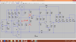
T3 and R14 removed. 23 volts and minus 23 volts are present as it should.
How should I check the voltage on R9? Where to put the second lead?
How should I check the voltage on R9? Where to put the second lead?
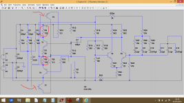
That's much to high. Keep everything just as it is and isolate T6 base and T7 base as shown here and then measure the voltage again.
The voltage on R9 should now be zero.
If it is not then leave things as they are and measure the voltage across R6 and across R8 by placing your meter leads across each resistor in turn.
Those voltages should be near zero. If you get to this point and there is voltage across R6 then T1 is faulty or there is a short on the board itself.
-------------------------------------------------------------------------------------------------
What is happening at the moment is that 22 volts is being fed to the output, and so we are isolating parts of the output stage in turn to see why.
Attachments
C3 minus to R9 after T6 T7 bases isolted now 15.6V
Interesting 🙂 You would get around 15 volts if T1 is conducting.
I have 4.7V across R6 and 0V across R8
Again, those are the readings you would expect if T1 is conducting.
T1 was replaced by me with the BC147A resistor. It's not a failure here.
😉 I want to be sure on that.
There are three possible ways T1 can be conducting and drawing current through R6.
1/ Its simply faulty.
2/ Its fitted incorrectly and some of the leads are mixed up.
3/ C7 is leaky and turning T1 on.
----------------------------------------------------------------------------------------
This is how we determine what is happening.
1/ Remove T1 and check that R9 voltage is now zero.
2/ Also confirm that voltage across R6 is now zero.
If those are now correct we test the transistor.
Lets get to this point first and if all is OK then I'll tell you how to test it.
- Status
- Not open for further replies.
- Home
- Source & Line
- Analogue Source
- Thorens 125 MK1. Help me please repair this PCB.