Which schematic sorry? I think I must have missed something. I've currently got the setup as per the other measurements i.e. laptop connected to the UMC via USB, which is connected to an input to my preamp via the UMC headphone socket, which is then driving the power amps to the speakers. The only difference today is that I've removed the crossover completely and currently have the power amp connected directly to the LF drivers only (not tried the HF yet). I can measure the SPL ok, just not the impedance.
Disconnect the amp. If the output gets shorted to ground (not unrealistic), you could end up in a mess.
Here's the relevant bit of the help file.
Impedance Measurement
It's possible to use the amp, but it's much safer (for the amp) not to.
Chris
Here's the relevant bit of the help file.
Impedance Measurement
It's possible to use the amp, but it's much safer (for the amp) not to.
Chris
If I'm understanding this right, I need to bypass my Cyrus system completely and physically wire the driver cable to the UMC?
How can I connect the speaker cable directly to the UMC input, is there an adapter that converts from wire to XLR? I'm also not sure how to split this to left and right, unless I use input 1 for left and input 2 for right, but then I don't have any inputs left for my microphone.
I'll have to buy the 100 ohms resistor as the largest one that I have is in the crossover and is only 5.6 ohms.
Thanks.
All this measurement boils down to what you are going to do to fix these things:
You may not know that Dissi is one of the World's best designers of simulators. He has evidently run your non-standard SEAS Thor woofers on his platform.
I would listen to him. At a certain point, if nothing much is wrong with a speaker, you just enjoy the music.
In my opinion an additional 1 ohm resistor is urgently needed at the input of the woofer filter in order to improve the frequency response of the woofers. Then adjust the tweeter level to your liking.
You may not know that Dissi is one of the World's best designers of simulators. He has evidently run your non-standard SEAS Thor woofers on his platform.
I would listen to him. At a certain point, if nothing much is wrong with a speaker, you just enjoy the music.
mcgi, I used a couple of 1/4" jack cables cut in half to make up the impedance jig. Yes, you need to remove the Cyrus gear. Impedance measurement does not require a microphone or anything else. Just the stuff shown in the link I posted above.
100ohm resistors are cheap - you only need a 1/4w one.
Chris
100ohm resistors are cheap - you only need a 1/4w one.
Chris
Hello system7. I didn’t really understand exactly where in the circuit the resistor was supposed to go to be honest. I’m actually (sort of) enjoying learning with the guidance of Chris.
Chris, I thought that I had sorted to jig out but I must be doing something wrong. I am getting a measurement but it’s just like an exponential curve. I’m not hearing any sound through the drivers either which I assume is wrong? On the circuit diagram, what do the circles signify, perhaps that’s where I am going wrong? Lastly, do I need to measure just one driver or can I leave both of them wired together?
Chris, I thought that I had sorted to jig out but I must be doing something wrong. I am getting a measurement but it’s just like an exponential curve. I’m not hearing any sound through the drivers either which I assume is wrong? On the circuit diagram, what do the circles signify, perhaps that’s where I am going wrong? Lastly, do I need to measure just one driver or can I leave both of them wired together?
I thought I spelled it out clearly enough:
https://www.diyaudio.com/forums/multi-way/356953-thor-speaker-lots-help-please-6.html#post6282483
The circuit mods in red:
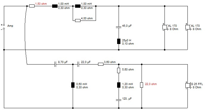
And what they do with similar drivers, dotted being original, solid being with mods::

Just takes the bass down a bit. What Dissi did was adjust for your bass unit Qts, which is not the original SEAS Thor driver. Still not convinced the tweeter LCR is right. I think I got nearer 68uF when I looked at the tweeter Fs resonance.
https://www.diyaudio.com/forums/multi-way/356953-thor-speaker-lots-help-please-6.html#post6282483
The circuit mods in red:
And what they do with similar drivers, dotted being original, solid being with mods::
Just takes the bass down a bit. What Dissi did was adjust for your bass unit Qts, which is not the original SEAS Thor driver. Still not convinced the tweeter LCR is right. I think I got nearer 68uF when I looked at the tweeter Fs resonance.
Steve, I'm sure I've pointed this out before, but simulating different drivers from a different manufacturer isn't an accurate way of predicting what will happen here. The acoustic measurements of the actual drivers in use bear little resemblance to your simulated curves.
With regards to the debate on LF loading, the OP has clearly stated that they're happy with the bass. Looking at the curves, there's ample bass (if it was mine, I'd reduce the level) in terms of level and extension and I see no sensible reason to start altering that.
mcgi, to answer your questions:
- You should hear a sweep (quietly) through the drivers.
- The circles on the schematic are the negative terminal of each input or output.
- Both drivers wired together is fine.
Some (hopefully helpful) notes:
- Make sure the input gains on the UMC202HD are matched. 12 o'clock is usually a good starting point
- 12 o'clock on the headphone output is also a good starting point. In REW, set the sweep level to -6dB and see how that goes.
- Make sure all the buttons on the UMC are OUT, and leave +48v switched off.
- Pressing "check level" in REW is a good way of making sure everything looks sensible. You should hear a sine tone followed by pink noise from the speaker.
- The test noises and sweep(s) will be quiet from the speaker. It's only a headphone amp.
- Any extraneous noises should be kept to a minimum. Speakers can (and do) act as microphones, and and signal they feed into the measurement system will screw things up.
Chris
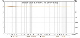
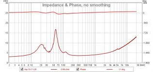
I seem to have made some progress as I can hear the faint noise through the speakers now, however as you can see from the attached, there seems to be something wrong with the measurement.
Perhaps I have my wiring incorrect still. To explain what I have done in my non-elecgrical terminology:
I have connected the XLR input 1 white cable (bottom pin I believe) one side of the resistor and the white cable coming out of the headphone jack. I have connected the other end of the resistor to the driver +ive cable, this cable feeding both mid bass drivers. Finally, XLR input 2 white cable to the driver -ive cable feeding both mid bass drivers.
Does this sound correct?
Attachments
It would be much easier to work with 1/4" jacks, but if we're working with XLR inputs:
Pin 1 = ground, pin 2 = +, pin 3 = -
Given that, you should connect pin 1 & 3 together to make it unbalanced. If you're using the XLR cables for other purposes, you should remove this link after doing the impedance measurements. Particularly, it'll stop phantom power (which your measurement mic needs) from working.
I'm not sure what you mean by "white cable". Are you referring to the inner jacket colour? What are the other colours?
You should have the headphone side of the resistor connected to input 1, pin 2, and the speaker side of the resistor connected to input 2, pin 2. You can safely connect all the negative terminals (headphone out, input 1, input 2, speaker -) together.
Chris
Ah, sounds like I misunderstood the diagram. Firstly, yes, the white cable is the inner sheath running from the XLR (and headphone) connection. I'm using XLR as its the only input connection on the UMC.
Up to now, I've not had the red inner cable from the any of the 2 x XLR or headphone cables connected to anything as I thought the diagram used only negative cables, as those round symbols are shown at all outputs?
Up to now, I've not had the red inner cable from the any of the 2 x XLR or headphone cables connected to anything as I thought the diagram used only negative cables, as those round symbols are shown at all outputs?
The UMC202HD has combi XLR & jack connectors.
The round symbols are to be viewed like phono connectors: centre positive, outer ground.
Chances are the red cable goes to pin 2, which is +'ve. Best to check.
Chris
The round symbols are to be viewed like phono connectors: centre positive, outer ground.
Chances are the red cable goes to pin 2, which is +'ve. Best to check.
Chris
Chris,
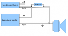
I'm even more lost sorry, however I've found the below diagram that does actually make sense to me. I can follow this but the problem that I have is that this shows 4 cables coming out of the headphone jack, but I only have one headphone jack and therefore two cables.
However, there are two 'output' jacks L and R in the back. I don't believe these to be headphone outputs but perhaps that is what I should be using? If correct, then I don't need to connect anything to the L side, just the R side. The only thing that I need to work out then is to do is connect which XLR pin to where. Pin 1 is 'earth', 2 is positive and 3 negative, which I have checked. So using your previous advice, I think that I just need to make sure that pin 1 and 3 are connected together at the end of both XLR cables?
Also, there areonly two inputs into the UMC, both of which being XLR.
Attachments
mcgi, I have two of these interfaces in front of me (well, one's a UMC404). It's an XLR/jack combi. You can plug a jack cable into the middle. See here: Would I buy it again? Review of the Behringer U-PHORIA UMC202HD Audio Interface - Plus 2x bonus gear! - Ben Lobaugh Online
Busy day coming up, but I'll get back to you on the rest soon. If all else fails, I'll post a cable to you.
Chris
Busy day coming up, but I'll get back to you on the rest soon. If all else fails, I'll post a cable to you.
Chris
I never realised that I could use a jack in this connection! That makes things simpler and answers one of the questions anyway!!
Alex
Alex
Hello Chris,
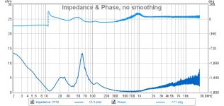
Just wondering if you think that the above measurement seems correct?
I'm going to try again this afternoon
Thanks,
Alex
Just wondering if you think that the above measurement seems correct?
I'm going to try again this afternoon
Thanks,
Alex
Hey Alex,
Can I ask how much your passive crossovers cost for the pair?
Also did you manage to them right first time or have you had to buy a lot of other components that are no longer needed?
Thanks and all the very best
Alex.
Can I ask how much your passive crossovers cost for the pair?
Also did you manage to them right first time or have you had to buy a lot of other components that are no longer needed?
Thanks and all the very best
Alex.
PS,
If you spend £400 new (£200 Ebay) on an amazing DBX PA 2 DriveRack PA2 | dbx Professional Audio it will solve all your crossover design and Eq / room tuning issues to tailor the sound / frequency response to your conservatory ( or any other room should you ever move the speakers)
Cheers
A.
If you spend £400 new (£200 Ebay) on an amazing DBX PA 2 DriveRack PA2 | dbx Professional Audio it will solve all your crossover design and Eq / room tuning issues to tailor the sound / frequency response to your conservatory ( or any other room should you ever move the speakers)
Cheers
A.
- Home
- Loudspeakers
- Multi-Way
- Thor speaker – lots of help needed please!