so you have confirmed two pairs of wires that make up two isolated windings. Screw these into adjacent terminals on the strip.joka22 said:okay for the secondary wires grey and blue conduct and the meter makes the sound and same for red and yellow. resistance over the same wires is (0.9ohm).
for primary leads brown and orange thier were no continiuity and no ohms reads zero.
okay purple and green read 1.3 ohm and does conduct on the continiuity test.
and for the black wire does not show ohm it is zero and does not conduct on the continiuity when joined to the white wire or green (white and green are joined together with spade crimp.).
You must now set about finding all the other pairs. You have no choice.
i know the secondaries wires are the blue grey red adn yellow all i just need to know if i need to join the black to the white wire for 230v primary setting for uk. i have emailed antrim but they have not replied.
lets say if does work yeah i am only going to use one secondary wire to power one dhr turbo and the other secondary just will be isoluted and unused, will this not affect the power supply oh am i okay to go head with this plan.
lets say if does work yeah i am only going to use one secondary wire to power one dhr turbo and the other secondary just will be isoluted and unused, will this not affect the power supply oh am i okay to go head with this plan.
you must find and confirm all the pairs before you do anything else.
Once you have the pairs identified and posted the resistances of each pair, we can guide you towards a successful conclusion.
Once you have the pairs identified and posted the resistances of each pair, we can guide you towards a successful conclusion.
yh they were 0,9 ohms the secondary wirings these the ones that come from one pair. they give 43vac each last time i measured (scavanged from a pa amp long time ago).
but what i cant rember if the white and black need to be joined to set the toriod into 230v or i just connect it without the white/black.
i think the one i got is the older toriod version and is us version 115v.
the only wires that are not shown on the antrim wiring scheme is the green/purple wires these wires i dont know what they for.
you have told us about three times you have confirmed the secondaries.
Now tell us you have confirmed the primaries and the other unknown windings and post the results.
We cannot do anything for you until we can identify what the wiring for the other windings is and then we can be quite clear and safe.
Did you build up the simple version of the bulb tester? We will need it!!!!!!!
oh the primary wires are brown and orange i know this becuase they were connected to the power switch on the old pa amp i had.
white/green (two wires connected as one pair) and black wire do not conduct or show ohms on the meter. the white/green are two wires that are connected to gether by a spade connector.
connecting the meter probes at purple and black show no ohms and no conduct on meter.
white/green (two wires connected as one pair) and purple show continiuity (conduct) and show 1.6ohms.
the black and white are from one pair and the green and purple are from one pair.
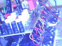
my dhr turbo amp bolted to the heatsink but wires were used to connect the transistors to the board since i had problem screwing them when on the board (not fully flat on the heatsink when on the board and screwed in or not alined).
2sa1943 / 5200 when you cut the middle leg to short the solder paste does not stick i had use a wire screw block and cut it out of the plastic container and pull the metal screw block out and place over the middle leg on the transistor and then screw in and then solder it to the wire.
the wires from the transistor help my circuit suspend over them so i do ned to bolt my board for support.
Attachments
Wire use to be a problem..is your amplifier operating fine?
I hope so...but i had problems when using wires... when they run touching the ground, along the heatsink (grounded)..then...having a heatsink as ground plane..then they use to work fine..but when they are aerial that way i had troubles.
I hope yours is working fine.
regards,
Carlos
I hope so...but i had problems when using wires... when they run touching the ground, along the heatsink (grounded)..then...having a heatsink as ground plane..then they use to work fine..but when they are aerial that way i had troubles.
I hope yours is working fine.
regards,
Carlos
Hi,joka22 said:2sa1943 / 5200 when you cut the middle leg to short the solder paste does not stick
the middle leg of a BCE Power transistor is physically and electrically connected to the heatsink face on the back of the device.
If you also have this device bolted to a heatsink and have cut the leg short, you will find it extremely difficult to get the leg upto soldering temperature.
Use a big soldering iron and heat it thoroughly.
Remove the heatsink.
Melt on a large blob of solder and when your ready, try to heat that middle leg very quickly to get your soldered joint.
I use to cut my transistor leads to avoid them to broke because of forces applied and
the weak point you have into the transistor case base..the place where the lead enters or exit the plastic case is a very weak point..there the transistor use to have the leads broken. (lever, a fulcrum)
So, i have 20 pairs, the ones i use to experiences, all them with cutted leads.
I use to melt solder into those short leads (3 to 4 milimeters long) when the transistor is out from the heatsink...over the workbench...them the solder melts with a 30 watts soldering iron, i keep the soldering iron tip for 4 seconds and them i melt the solder to cover all short lead, to be covered by solder both sides...and the result must be clean and brigth.
After that, it is not more hard to solder a wire (If not too much thick) even when your transistor is mounted into the heatsink.
Well...my environment......other places may be different..i think in Sweden, or North of Europe...even into the summer this may be very difficult to be done.
regards from sunny Brasil.
Carlos
An externally hosted image should be here but it was not working when we last tested it.
yeah i did try that by taking transistor off the heatsink but iwas still having problems my sodlering is temperature controled i got the hot air station two in one anyway solve it by using tremnial screw block.
carlos you know the hot air station i got it has a varible 15dc volt power supply on it could i use this to test my dhr turbo would i need to use caps on the psu wire to ripple the current. cos normally u use bridge rectifier to convert ac to dc n dn caps to ripple supply current but this is already dc volt may just ned cap on the end and connect to dhr turbo and slowly turn up the voltage to activate the amp. what you think?.
carlos you know the hot air station i got it has a varible 15dc volt power supply on it could i use this to test my dhr turbo would i need to use caps on the psu wire to ripple the current. cos normally u use bridge rectifier to convert ac to dc n dn caps to ripple supply current but this is already dc volt may just ned cap on the end and connect to dhr turbo and slowly turn up the voltage to activate the amp. what you think?.
No!.... better not to do that... 15 volts is very low voltage
The amplifier works with simetrical...and less than 25 plus 25 volts..or 25 volts positive, ground and 25 volts negative , will not be good.
Do the correct way.... use your big supply, but install a 10 to 22 ohms, 10 watts resistances into the rails (2 resistances)...this is the method we have to protect the amplifier....if the amplifier has short circuit, all voltage will be over the resistance...tbe board will have a few milivolts and many amperes circulating.
But power...is the result of multiplication of volts by the amperes...so....... 0.005V (5 milivolts) multiplied by 10 amperes (short) will result in 50 miliwatts into the board (circuit)..but the resistance will have 60 volts and 10 amperes.... into the resistance you gonna have 600 watts (not really because transformer will have enormous drop of voltage) and the resistance will smoke fast in this way..will overheat and will smell and you will fast notice that something is wrong.
Use the method aproved by thousands of audiophiles, along those last 50 years...do not create new methods..please..follow the instructions to avoid problems.
You have enormous change to smoke all that stuff, as you are not deeply skilled...do not increase, please, your chances of fire!
regards,
Carlos
My 12 years old daugther is packing the home theater that i will send to my sister in Brasilia.
An externally hosted image should be here but it was not working when we last tested it.
When the amplifier is fine..then you gonna have 1 volt into the protective resistance
The amplifier will have all the supply voltage less that 1 volts that will be developed over the resistance (in series with the supply)
100 miliwatts will be over the resistance..this gonna be the dissipated power.....
Why so big resistance...that 10 watts big resistance?
Because sometimes you can misadjust and the amplifier can drain 3 amperes... and this mean 30 watts...much more than the resistance possibilities...BUT... we do mistakes during small time.... having the meters plugged, fast you gonna notice the voltage that must be 1 volts will be measuring much more..and you will turn fast the adjustment trimpot to the other side or will switch the supply off to obtain some time to be thinking about.
30 watts into a 10 watts resistance..for 5 seconds..will not burn it in flames.
Remember..when everything goes fine, the voltage over the 10 ohms protective resistances (both of them) will be around 1 volt DC.
Enormous voltage means error....wrong parts or wrong circuit....or wrong stand by current adjustment.
If you do not understand what i am saying..better to call a more skilled friend to do those adjustments to you.
Use 20 ohms...and them the voltage will be 2 volts..... using 20 ohms the normal voltage will be 30 Volts (more or less)
To switch power on, without protective resistance will represent 95 percent of chances the whole stuff explode!..will loose parts and board will have a black hole into the middle!
regards,
Carlos
right added negative and postive resistance 10 ohms and 3 watts but when joining the ground wire from transformer to speaker ground i get humming sound and light bulb lights up dimly. if i do not join this wire one side of the board led wont turn on. my mulitmeter read 20 dc volts on rail.
and dc offset is at like 300milivolts.
and dc offset is at like 300milivolts.
The bias trimpot must change that 20 volts, or increasing or decreasing
doing this way, you will know the bias circuit is operating.
big differences of currents from rail to rail is because of errors into the construction.
Check the amplifier... follow the copper lines and trace with red pencil or pen into a printed schematic, to be sure all lines are there.
Give a tripple check into transistor leads.... If you replace, for instance. 2N5401 by a BC556, the leads goes inverted..check all that stuff, resistance values and so on.
Go marking into the schematic all you do, to be sure you have checked everything..also check your supply polarity..if you're having the positive into the positive rail and the negative into the negative rail..this happens a lot...even with skilled people, to invert things.
regards,
Carlos
Check for shorts under the board too
clean the boards and observe them using lenses.
regards,
Carlos
clean the boards and observe them using lenses.
regards,
Carlos
update to carlos
hi carlos as i was trying to figure out why the amp is not working i touched the capacitor the one for input signal that joins to this the capacitor is 100 volt 220uf it was hot.
anyway i stripped out all the semi conducters (2n5551, 2sc3423, 2s1837 etc) and replaced them with new ones.
found 10 ohm resistor burnt that joins at the gnd of the input replaced this now.
and checked the 2sa1943/5200 transistors for shorts and did diode testing approx 0.6v i was getting they seem fine.
transformer (approx 20vac i think) is old kenwood trio amp part i slavaged since the big toriod i had has seemed to have died.
board has beenn wicked cleaned.
took me all day just taking the wires from board to transistors the wires have been replaced with the internet cable type wires which are alot neater.
big test is tomrow since in my house we got them light effecent bulbs they do not fit my bulb holder hav to go n buy the 60w cheap type bulb for testing then i will report and update over here.
Long wires to transistor, say, more than three inches, use to be a problem
in special if they run paralel, as this creates capacitances...make them as short as you can, install the board almost touching the heatsinks to avoid long run of cables.
VAS must be into the board..cannot connect drivers using wires... guarantee of oscilations if you do that way.
Your driver is high speed...use a bigger miller capacitor if you have oscilations (AC measured into the output, with no signal into the input, power transistors hot... high current into stand by mode..or oscilations triggered by the input signal while operating)
Oscilations triggered by the signal is easy to happens, and usually you find into several amplifiers, as this produces an interesting reverberation alike effect...but it is a deffect and must be avoided and inspected using osciloscope...during stand by mode the current and off set is normal..and you feel safe..but when audio enters, some frequencies (high) triggers the circuit that starts to oscilate..audio turns different, compressed and mufled, sometimes harshing..i do not like the effect..i felt as defect..but some people use that to produce the "effect"
It seems you may not have used protective resistances..yeah...i may be wrong..but looks alike....because they avoid resistances to be burned, even when they are misplaced or connected from plus to minus.... the protective resistance takes the power and do not let parts goes burning into the board.... when you have shorts into the board, then the resistance tooks to itself all the voltage and the current crossing make the protective resistance very hot..but into the board you gonna measure milivolts only..and milivolts multiplied by several amperes result in a few miliwatts...normally this does not burn parts and boards.
Never connect boards recently assembled without protective resistances..you may destroy many parts and this will increase your work debuging, as you may have not only errors,but also shorted components...will have to remove all transistors and test them outside the board..a lot of hard work..bigger than to find,buy or provide protective resistances..i hope you're using them for your own good.
Bring the fire extinguisher near you if you intend to connect the circuit without protective resistances.
Bulbs?... are you using them as protection?...in series with the mains or in series with the DC supply output voltage?...sometimes works... and works both ways.
Good luck!
Carlos
The cobalt blue line, the lifted input ground, is exclusive...
to the coaxial input audio cable shield...do not connect zobel there and to not take the output cable ground there..only to the input audio cable shield.
In some circuits, alike your kenwood, the shield is directly connected to the main ground..in this case your lifted ground turns non effective and noises may enter the amplifier.
Using kenwood transformer, connected to kenwood boards..the transformer center tape will be at ground level, will be soldered or attached to the chassis...so, when you connect that shield to the input you will be connecting that point to the ground too and shorting the 10 ohms resistance.
The lifted ground works fine when you have a separated, remote, audio source..then you have one ground that comes from audio source and other from your own power amplifier transformer.
Also the input audio connector ground must be insulated to the chassis, or you will not have the lifted (lower noise) input ground.
The schematic is not the DHR Turbo..this one is the Dx amplifier..but the input ground is the same in the Standard, HRII, Precision 1 and DHR Turbo.
regards,
Carlos
An externally hosted image should be here but it was not working when we last tested it.
well carlos i erm attached the input to computer and played music this time again but nosound so i touched the heatsink i get faint sound loud enough to hear but the bias piot is no good i turn it but no use it dnt do anything. it seems when i touch the bias pot pins n heatsink at the same time i get some faint sound evrything cool not hot i then tried this trick attach wire on one of the pot wire and to heatsink sound came thru but weak souind but you can hear the music.
1. sound output gnd wire is attached to transformer tap center.
trasnister seem healthy no heat. but putitng my finger on the trans connections seems to bring some weak music sound to speaker.
bulb light tunrs off completely when i try some of this tricks.
tranister wire to board are 5 inches long i cnat attach the transister to board nomore due to very shiort legs.
- Status
- Not open for further replies.
- Home
- Amplifiers
- Solid State
- This is the DHR.... Dx High Resolution Turbo