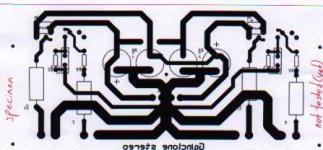
Any comments on my layout are welcome. This is not the final board because sizes of parts are still unknown. Have to buy the BG's. I know the Gainclone is supposed to be hardwired but I simply don't like hardwiring.
I deliberately used a low resolution to prevent anyone from using this unfinished and untested layout. If it has reached the final stage I am willing to publish it here for anyone to use.
I deliberately used a low resolution to prevent anyone from using this unfinished and untested layout. If it has reached the final stage I am willing to publish it here for anyone to use.
I don't see your feedback resistor, is it soldered directly between the pins (it should be). Also I would try to move PS caps closer to the chip. BG are bigger than the footprint you are using. You might also find that the amp sounds better with positive input connected directly to the ground (in inverting mode).
i still haven't heard of any who tried to parallel several lm3875 to get more power.....??????
and how about using bigger caps...???? 10.000uF - ?
bigger transformer...?

and how about using bigger caps...???? 10.000uF - ?
bigger transformer...?
Sorry, I scanned the layout another time for better viewing.
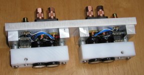
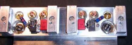
Feedback resistor is mounted between the pins, Peter. Never mind that I don't like hardwiring. If I could do is as neat as you can I might consider it. Plan is to snip off some of the unused pins for a better layout. Positive input can be shorted to ground by using a jumper wire instead of a resistor. The 1 uF caps have to be mounted at the copperside. Remember this is a first version ! It will be more compact and it will have shorter tracks. Distances of components look greater than they are in reality. Just showing it to you for comment ( and good ideas ). Power caps are moving to the chips as I speak 😀
Footprint is wrong for BG, I know. The ones I have here have the used footprint. I want to use 4 x 1000 uF as you can see. Wires will be connected with those plastic blocks in which you can attach the wire with a screw ( don't know the english name for it ). Although there are very few parts it is not easy making a nice board that's symmetric ( ish ).
Transformer will be a Seidlbauer 2 x 18 V 4,44 A.
Attachments
Well, since there is going to be a little delay on the AX boards, I think I am going to build one of these little suckers now. Since, I have the passive components already, I guess I don't have any excuse. I got nearly all the rest of the square tubing for the heatsink project and need to cut it up. I might as well cut out a gainclone chassis.
Peter, how long did it take to get the amp samples after you asked for them?
Peter, how long did it take to get the amp samples after you asked for them?

Scott Nixon sells pc boards for a gainclone.
http://home.triad.rr.com/scottnixon/dac.htm
Go to the bottom of the page.
Jam
P.S. Peter I still say you could make a fortune selling gainclone chassis
http://home.triad.rr.com/scottnixon/dac.htm
Go to the bottom of the page.
Jam
P.S. Peter I still say you could make a fortune selling gainclone chassis
I built a gainclone a while ago, when everyone on this board say that it would suck because it was an IC and an opamp. Oh well, it was simple, and my first project so I did anyways, I liked it. And I've built others since then. Although I've only seen LM3875s in this thread I prefer the LM1875, less power but I think they sound better, just my opinion though. But I do rather my Class-A MOSFET Power Follower to my gainclones. So I guess we all have our own opinions.
Jean-Paul,
I had a friend build a discrete version of a gain clone. It sucked, food for thought. There is a lot to be said for keeping the layout as compact as possible.
Jam🙂
I had a friend build a discrete version of a gain clone. It sucked, food for thought. There is a lot to be said for keeping the layout as compact as possible.
Jam🙂
jam said:
P.S. Peter I still say you could make a fortune selling gainclone chassis
How about finished gainclone?😉
Whre is Thorsten's circuit?
Hi all. How does Quality Kit's LM1875-based kit compare to the Thorsten circuit? I have bought two and a 220 VA Vellemen xformer and Quality Kits power supply (40000 mF) but the chassis is the stumbling block. Also where is the Thorsten circuit available?
Oh Peter: great chassis...just simply humbling. Do you ever anodize parts? How do you prevent long-term corrosion of raw aluminum faces if not by anodizing. Thanks.
Greg Olsen
Calgary
You'll find Thorsten circuit here: http://home.student.utwente.nl/f.s.bouwman/audio/thor-amp.html
You don't have to anodize. I have bare aluminum staff from 20 years ago and it doesn't have any traces of corrosion.
You don't have to anodize. I have bare aluminum staff from 20 years ago and it doesn't have any traces of corrosion.
I have a question:
My next gainclone would be based on double 18V secondaries transformer with separate bridges for positive and negative rails. Are 60V rated Schottky diodes OK?
My next gainclone would be based on double 18V secondaries transformer with separate bridges for positive and negative rails. Are 60V rated Schottky diodes OK?
Hey Peter,Peter Daniel said:
How about finished gainclone?😉
How about finished Gainclones amps thru your friends at the Parts Connexion and chassis to your friends at the DIYAudio forum.
Just a thought,😀
Rodd Yamashita
- Status
- Not open for further replies.
- Home
- Amplifiers
- Chip Amps
- This is not just another gainclone