Wait a minute! A fairly minor revision of the grounds is NOT tearing the thing apart for god sakes! And what is the deal with pride? Rarkov, pride is not good when it doesn't allow you to accept some constructive criticism and to make whatever you are making better. I don't care what Peter does with his amp, he can roast chestnuts on the heasinks as far as I am concerned.
Ok Peter, that's not true, I do care, I am just making a point here.😉 I also think that you will eventually get around to make some changes just becouse of your uncompromising nature.
As far as I am concerned I know better than to rely on my poor engineering skills and I always try to keep the design open to small mods that may improve preformance.
As to the issue at hand I found that changing conductor type, length and layout makes an enormous difference in terms of noise.
In my case it was not the noise that appears to be the problem. Either star point or rail connect in series both have no audiable "noise" over one to the other.(Sorry no scope in hand)
But for using the rail connect in series with large caps strangled the Hi and compressed the dynamic of the music to my dislike. With the star or like you folks refer to zero potential between each cap relative to the power rail give me all the dynamics and I can use more caps, thus better bass define and sense of power. (make sure each wire has equal length was the key in the star point method). May be this is what Andy(ALW) talks about placing extra ripple for the first cap to handle and something regarding the conduction angle...
So may be it was the noise that have the impact, I have no idea, but I am happy that I can use up all the caps that I bought for the amp and the music was good by using the star point method over the connect in series onto the rail.
To me it was the characteristic in sound of the amprefier the two methods have different effect upon.
Regards,
Chris
No offence taken in any way😉 , I'm always open to suggestions and improvements. But if I wouldn't make it this way, and possibly improved later, I wouldn't know about the sonic difference if possible. I always wanted to make true star ground and power rails for caps, but you know how it usually turns out in reality. At some point you just want to quickly finish your project and hear thr results.😉
As to the wire gauge, I would use the thickest wire, which still provides convenient connection and soldering.
As to the wire gauge, I would use the thickest wire, which still provides convenient connection and soldering.
Infinite Ground....
In my experince using a large copper plate works very well for the ground common, and can make a better grounding scheme than practical star techniqes.
Art shops sell thin copper sheet for embossing purpose.
If using thicker plate, then making two cuts about 6mm apart to make tags helps soldering to this plate easier - hot air paint stripper gun too to preheat the sheet.
I have also used copper tube as busbar and this worked very well for supply rails.
Eric.
Hi,
Didn't realise I was going to get flamed!
I retract my earlier comment...Of course anyone has the right to do what they like with their own work...Myself, I would like to leave it for a while until I knew my 'new' system inside out and back to front...
But that's just my opinion...
Thanks
Gaz
Didn't realise I was going to get flamed!
I retract my earlier comment...Of course anyone has the right to do what they like with their own work...Myself, I would like to leave it for a while until I knew my 'new' system inside out and back to front...
But that's just my opinion...
Thanks
Gaz
Peter,
I would not worry to much about the hum if its only just audible.
In my Aleph 2 arrangement the ac & earth goes in one end of the parrellel capacitors and comes out the other end with earth and ac. I found this the best for lowest hum on advise from Doug Self.
cheers
macka
I would not worry to much about the hum if its only just audible.
In my Aleph 2 arrangement the ac & earth goes in one end of the parrellel capacitors and comes out the other end with earth and ac. I found this the best for lowest hum on advise from Doug Self.
cheers
macka
Attachments
Rarkov said:Myself, I would like to leave it for a while until I knew my 'new' system inside out and back to front...
And that's exactly what I'm doing.😉
And thank you for your previous post.🙂
Tha noise of the rain on the tin roof often sounds like music,
but also often more like the sound track to Niagara falls.
For me, the same feeling comes with hum and buzz.
The clean air on the tin roof could be always better.
JH
but also often more like the sound track to Niagara falls.
For me, the same feeling comes with hum and buzz.
The clean air on the tin roof could be always better.
JH
I am starting to put together a power supply for my aleph-x, and I am using those fairchild diodes. What value capacitors did you use in your rectifier circuit here:

You also mentioned not having space for resistors, what was this for?
--
Brian
You also mentioned not having space for resistors, what was this for?
--
Brian
Brain,
the resistors are used in series with the caps to dampen the overshoot. There´s a link somewhere to an article called "Calculating Optimum Snubbers". It´s all explained very nicely and after reading it I would make some space for those resistors.
william
the resistors are used in series with the caps to dampen the overshoot. There´s a link somewhere to an article called "Calculating Optimum Snubbers". It´s all explained very nicely and after reading it I would make some space for those resistors.
william
Someone should write to the author and tell him to straighten the equations out. Time series and Bessel functions are not the world easiest topic to follow through as it is. I am going to check out the cornell-dublier file.
Hi William,
>the resistors are used in series with the caps to dampen the >overshoot. There´s a link somewhere to an article >called "Calculating Optimum Snubbers". It´s all explained very >nicely and after reading it I would make some space for those >resistors.
I do have that article, and I did read it...
My problem is that I have absolutely no idea what figures I should use for my torrodials...
In an Aleph 5 I use two 330 VA 30 VAC torrodials by Reichelt:
http://www.reichelt.de/index_direkt.html?RKT 33030+Pfto16wQAQsAAGHC0uw+C55
In an Aleph 4 I will use two 750 VA 30 VAC torrodials by Thel:
http://www.thel-audioworld.de/bauteile/trafos/trafos.htm
I did not see any data on how many resistance, inductance etc.
Do you have any idea what would be realistic values for those calculations?
With kindest greetings,
Lucas.
There are also some threads about snubbers on the forum. You can find them doing search under "snubbers".
Peter,
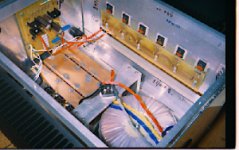
I was looking at some of the Aleph-X pictures that you posted on this thread and I noticed that the weight of the whole amp is basically supported by the 4 stand-off that are located right below the transformer. Could you explain why you did it that way?
Edit: But then again I don't see any feet under the bottom plate or is there? If no feet, then I would say the weight of the amp is supported by the heatsink.
The weight is indeed supported by those 4 standoffs. Under the standoffs, there is a bottom plate and 4 feet. The same screws attach the plate and feet to the standoffs. Actually, it's the mid-plate that supports most of the amp: transformer, PS caps, heatsinks, front-end board. Everything is attached to this plate and the plate itself rests on those standoffs.
I did it that way, because I like simplicity. Taking in consideration that the standoffs are 1/2" brass, I don't thing it's too much weigh for them to support.😉 Also the plate makes the whole assembly more rigit, comparing to standoffs alone.
I did it that way, because I like simplicity. Taking in consideration that the standoffs are 1/2" brass, I don't thing it's too much weigh for them to support.😉 Also the plate makes the whole assembly more rigit, comparing to standoffs alone.
I just have the first Channel of my 100W-Aleph-X assembled, not tested yet. I would like to take Peter' thread as here a couple of good advises have been documented already to ask two questions:
1.) For unbalanced connection I understand that you have coneect simply a inout-cap before the positive input. Ground of the RCA-Plug to ground of the circuit and Minus-input attached to ground with a cap same size as the cap at the positive input plus a 100Kresisor in parallel to ground.
From Nelson I understoof that the DC-conditions have to be the same on the input of the negative and the positive side, so I understand that you have coupled the negative input through the 100K resistor to ground like in a tube amp, but for what is the coupling-cap to ground good as there is no signal ?
2. Is there a good description on the start-up tests ? What I have so for on my notes:
0. Shorten input to ground
1. Check Target Voltages of the rails
2. Check Bias of the Fets
3. Check on each side absolute offsets and adjust through the 100ktrimmer
4. Check absolute offset and adjust through the 200RTrimmer of the current source
5. Check temperature
6. Repeat of all of the above after 30min and after 2 hours of operations
7. Check ripple
8. Check voltage over the 392R resistors, should be more 5 V than 4V
Anything else ?
Best Regards
- Status
- Not open for further replies.
- Home
- Amplifiers
- Pass Labs
- This is not just another Aleph