fcel said:Peter,
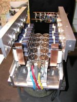
Do you have 8 transistors mounted on the bottom side of the chassis (can't be seen from the pictures that you just posted) to get you 16 transistors per chassis?
He posted this before. 4 per bank = 16 total.
--
Brian
Attachments
BrianGT said:Has anyone gone as far as make a Fruglephile(tm) amplifier?
GainKlones count as Frugal-phile(tm). So do Pheonix amps (tube amps resurrected from old console amps), and i suspect that a ZEN could be done on a Frugal-phile(tm) budget. I am sure their are more examples. In all cases it is more of finding cheap iron and (for SS) cheap heatsinks -- dead computer monitors can come in handy here, or if the amp is small enuff , the aluminum backing dish you are using as a chassis will do the job.
dave
Dave,
With the price of second batch boards for Aleph X, 4 devices per channel, 250VA transformer per channel and cheaply obtained heat sinks, Aleph X qualify for Frugal-phile(tm) in my book as well.😉
With the price of second batch boards for Aleph X, 4 devices per channel, 250VA transformer per channel and cheaply obtained heat sinks, Aleph X qualify for Frugal-phile(tm) in my book as well.😉
Peter Daniel said:Dave,
With the price of second batch boards for Aleph X, 4 devices per channel, 250VA transformer per channel and cheaply obtained heat sinks, Aleph X qualify for Frugal-phile(tm) in my book as well.😉
That's a good point. In fact, I'm hoping to build a no-frills
2-channel Aleph-X (decent but non-exotic parts...and some
surplus items) for <$300 USD.
Dennis
Hi Peter
I do not remember whether you mentioned about the sound on the idling condition.
No hum, no buzz?
JH
I do not remember whether you mentioned about the sound on the idling condition.
No hum, no buzz?
JH
No buzz, I had substantial hum when caps on both inputs were not mached (.06u and 2u). Currently I have very slight hum, which is not detectable from listening position. There is no hum when I switch the amp on, and then it gradually emerges. I suspect that happens after thermistors warm up. Maybe 120,000u per channel is not enough?😉
Your amp has total 10 large caps with wire rails. The terminal of the wire rails is at the one end. I suppose it might be the cause of the hum if you hear it when the source is disconnected. I would have the terminal at the center of the cap complex. What do you think?
JH
JH
I don't know, but it would be too much trouble to rearange it. The hum is so low that it doesn't bother me.
For your information, when nothing is connected to the amp the hum is unexceptable, but I guess it's a part of the design.
For your information, when nothing is connected to the amp the hum is unexceptable, but I guess it's a part of the design.
Your amp has total 10 large caps with wire rails. The terminal of the wire rails is at the one end. I suppose it might be the cause of the hum if you hear it when the source is disconnected. I would have the terminal at the center of the cap complex. What do you think?
JH
I agreed. I have just completed the re-wiring of those caps on my JLH power supply which I complainted that I could not used more caps like 3 X 15000uf per rail for it strangled the highs and loss of dynamics. Now I can used all the caps I want. I used to have those caps in the same arrangement as the ones in Peter's picture with two wire rails. Now I change to wire indivdual cap's to a star point, make sure all wires are exact equal length to the star point. One star point to connect to the middle of the rail. Really clean up the sound a lot. I should say it does not mess up the sound instead. I was grinning cheek to cheek yesterday. The hair in the back of my neck stands again!!.
Chris

P.S. no inductor needed....nor series resistor yet
If this is the case, it will be an exercise for my next project.
I'm actually using 48 caps in ea. amp and I don't have a time to mess with them.😉 Good info Chris. I was always thinking about that type of arrangement, however, convenience was always winning, but not the next time...😉
I'm actually using 48 caps in ea. amp and I don't have a time to mess with them.😉 Good info Chris. I was always thinking about that type of arrangement, however, convenience was always winning, but not the next time...😉
Peter,
don't get lazy on me now, between the p2p, the heatsinks the time you put into it, you got $1500 bucks of exotic parts and maybe 100hrs of work in the AX, the kind of sloppiness in the GND connections is inexcusable. I am gonna loose faith in you if you do that! 😉
I looked at the AX picture, it wouldn't be too bad to beef up the GND connection of the skinned caps you can use the Cu strip that you use for the rails. Are you out of that? No problemo, if you give me the measurements I can send you a couple of pieces of Cu plate 1/32 thick to use as ground plane (OFC and FOC). You gotta get rid of the standoff thugh.
The best I can do to keep you guys happy is to cut those wire rails in half (at the center) and use additional wires to connect them to common point at the bridge. This way I'll reduce the problem by half.😉
I was also thinking about removing 100ohm output to ground resistors. They are using the same ground rail as the input and this may cause problems too. The DC is so stable that I might be able to do without them. I'll try it today.
I also suspect that my caps bank is not big enough. Because of the nature of the amp it should be at least doubled by regular standards.
Peter,
I always wondered about the wire gauge, in my experience the GND Gods are only happy with Cu plates. 😉
I always wondered about the wire gauge, in my experience the GND Gods are only happy with Cu plates. 😉
No offence to everyone else here...But I wouldn't be too happy if I were being pressured to cut up work that I was extremely proud of!!!
Keep it the way u want it Peter!
Gaz
Keep it the way u want it Peter!
Gaz
It's not an issue of pride. I wanted my amps to be built properly, yet one always have to choose compromise at some stage. For me it was acceptable way to do it, so I did it. We still don't know if different way of arranging things will be detectable sonically and I don't know if it's worth the trouble. Actually it's better to leave it this way and built another one with improved layout and compare the differences.
This bank of capacitors is only auxillary. It is 28,000u. The main one is close to output stage and totals 36,000. The main currents don't flow through copper wire rails (ga 12) because it is paralelled at the bridge only. From bridge the thermistor feeds the main rails.
This bank of capacitors is only auxillary. It is 28,000u. The main one is close to output stage and totals 36,000. The main currents don't flow through copper wire rails (ga 12) because it is paralelled at the bridge only. From bridge the thermistor feeds the main rails.
I completely agree with that, it's my experience too.grataku said:Peter,
I always wondered about the wire gauge, in my experience the GND Gods are only happy with Cu plates. 😉
ciao,
Roberto Amato
I have never uased the Cu plates. Instead, I always make symmetry about the center so that the electric potential is to be virtually zero at the center where half symmetry and another half symmetry see each other with the same electric potentials (say, local super symmetry). I do not care the wire gauges if they are thick enough to carry the current.
JH
JH
Either ones. The aim is to have the zero potential truly zero on all components concerned. If you have screw-type-contact condensers a CU plate it's surely more practical... the other way around with soldering-contacts kinds.jh6you said:I have never uased the Cu plates. Instead, I always make symmetry about the center so that the electric potential is to be virtually zero at the center where half symmetry and another half symmetry see each other with the same electric potentials (say, local super symmetry). I do not care the wire gauges if they are thick enough to carry the current.
JH
It's just that a CU plate is so much more handsome...😉
ciao,
Roberto Amato
Peter Daniel said:It's not an issue of pride. I wanted my amps to be built properly, yet one always have to choose compromise at some stage. For me it was acceptable way to do it, so I did it. We still don't know if different way of arranging things will be detectable sonically and I don't know if it's worth the trouble. Actually it's better to leave it this way and built another one with improved layout and compare the differences.
This bank of capacitors is only auxillary. It is 28,000u. The main one is close to output stage and totals 36,000. The main currents don't flow through copper wire rails (ga 12) because it is paralelled at the bridge only. From bridge the thermistor feeds the main rails.
You did a great job on the amplifier. I wouldn't be tearing it apart this soon. Enjoy it an listen to it! Thanks for the encouragement for getting me to work on finishing my version of the Aleph-X.
I was at Home Depot, and they have bare solid copper conductor wire 14ga up to 4ga. Would the thicker copper wire be better for the capacitor bank? I was planning on tieing them together in a similar arrangement. Would I be better just using multiple strands of normal 18ga wire and making a star arrangement?
--
Brian
- Status
- Not open for further replies.
- Home
- Amplifiers
- Pass Labs
- This is not just another Aleph