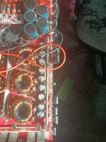
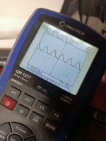
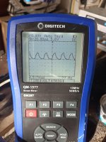
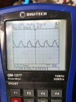
The first one looks as expected. The other two don't look like they're loaded with the capacitor.
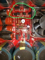
Centre image is on the fets that survived. Left pic is of the bank that blew but now has that small cap. And right pic is bank that blew with no cap
The center image appears that there is a diode in parallel with the gate resistor. That would be an odd configuration.
At this point, I'll say that it appears that there is a problem. Testing in this way generally causes all waveforms to look like the one on the left.
Without more information on the amp and the drive circuit, it's going to be difficult to offer any more suggestions.
What make/model amp?
HAve you tried to get the schematic diagram from the manufacturer?
For higher speed circuits like the output stage, yes. For the low-frequencies used in switching power supplies, they're not as common. I didn't see any in parallel with the resistors in the photo but mentioned them because it's possible they exist elsewhere.
The thing is, is that the two drive waveforms are different.
The thing is, is that the two drive waveforms are different.
Hi Perry it's an Orion hcca 8k.
Keep in mind I'm comparing waves with fets in that survived vs probe on the gate with no fet in place. Should I take all the fets out and recheck?
Keep in mind I'm comparing waves with fets in that survived vs probe on the gate with no fet in place. Should I take all the fets out and recheck?
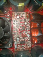
This is the driver
There are some NPN and PNPs under the board. But they check out are not shorted and visually look fibe
There are some NPN and PNPs under the board. But they check out are not shorted and visually look fibe
Attachments
Last edited:

I don't see the driver transistor.
Are you loading the other locations that have FETs with the loading capacitor? That could be one difference.
Are you loading the other locations that have FETs with the loading capacitor? That could be one difference.
Last edited:
No the locations that still have fets are left as is. I only loaded the spots that are missing the fets with the cap
Q703. 701 702 704 are the buffers
I only have 1 cap so can only test 1 at a time and as 8 fets came out thats 2 banks of high and low
Q703. 701 702 704 are the buffers
I only have 1 cap so can only test 1 at a time and as 8 fets came out thats 2 banks of high and low
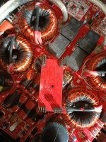
Where are those buffer transistors?
Why didn't you load with the capacitor in the other location?
Why didn't you load with the capacitor in the other location?
There the buffers and have a direct link to the gate legs.
Well there may be stuff in the path but I get continuity
Both NPN and PNP. 2 of each
Well there may be stuff in the path but I get continuity
Both NPN and PNP. 2 of each
Attachments
Last edited:
Where are those buffer transistors?
Why didn't you load with the capacitor in the other location?
That will be my next step however I think I'll get the same wave from all banks (missing fets)
I wouldn't think that that's enough to drive all of those FETs.
Move the capacitor to Q723 and post the gate waveform there.
What's the resistance between the gate of Q721 and Q723?
What's the resistance between the gate pads of the two outside missing FETs?
Move the capacitor to Q723 and post the gate waveform there.
What's the resistance between the gate of Q721 and Q723?
What's the resistance between the gate pads of the two outside missing FETs?
That's all locations missing fets with cap in. Same across the board. I just gotta go help a mate with a flat battery I'll check those other things u asked when I get back in like 15 mins
Attachments
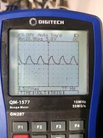
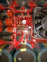
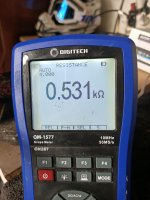
That's the wave on q273 with cap in. Also resistance between gates of q273 and q274
Like mentioned the gate resistors although they check fine at 265ohm have taken quiet a hit so will be swapping them when they arrive
Like mentioned the gate resistors although they check fine at 265ohm have taken quiet a hit so will be swapping them when they arrive
Attachments
Last edited:
Sorry read wrong between 21 and 23 is showing OL
With cap in amp off
All the rest are showing the pic above resistance even the fet banks that survived. The only one showing OL is with the cap in
With cap in amp off
All the rest are showing the pic above resistance even the fet banks that survived. The only one showing OL is with the cap in
Last edited:
- Home
- General Interest
- Car Audio
- These class D drive waves look normal??