Hey guys just repairing an Orion 8k that had a few blown power supply fets. (8 of 24)
I got rid of the shorted fets and now powers up fine. However I just noticed this.
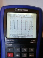
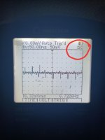
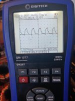
2 different drive waves indential on both banks that blew. Vs the banks that survived.
Is this just coz the fets are not in?? The drive chips seems fine and also the npn and PNP buffers
I'd assume it's different just coz I don't yet have the fets in the bank but just wanted to make double sure ...
(The less square wave is on the bank that survived )
Cheers guys
Edit. I'm still learning about all this amp repair stuff. And as I have only recently acquired a scope id like to make sure it's correct before fitting new fets just to watch them go up in smoke.
Am using a very small power supply to try protect stuff
I got rid of the shorted fets and now powers up fine. However I just noticed this.
2 different drive waves indential on both banks that blew. Vs the banks that survived.
Is this just coz the fets are not in?? The drive chips seems fine and also the npn and PNP buffers
I'd assume it's different just coz I don't yet have the fets in the bank but just wanted to make double sure ...
(The less square wave is on the bank that survived )
Cheers guys
Edit. I'm still learning about all this amp repair stuff. And as I have only recently acquired a scope id like to make sure it's correct before fitting new fets just to watch them go up in smoke.
Am using a very small power supply to try protect stuff
Attachments
Last edited:
Two things.
Drive waveforms on AC coupling are essentially useless. You must know where the ground reference is.
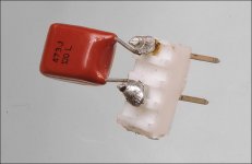
I'd suggest that you load the FET locations from G-S with a small capacitor. I use a 0.047uF. Anything close is OK.
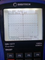
Repost the waveforms using DC coupling, the trace centered vertically, 5v/div and 20us.
Drive waveforms on AC coupling are essentially useless. You must know where the ground reference is.
I'd suggest that you load the FET locations from G-S with a small capacitor. I use a 0.047uF. Anything close is OK.
Repost the waveforms using DC coupling, the trace centered vertically, 5v/div and 20us.
Yes I'm not very familiar with using the scope just yet I just had the ground on the ground input. Saw a wave and thought I had a win 🤷*♂️
Where should I get the ground reference from? On 5v and 20us and DC copling the scope can not find anything
Oh and if you do not mind. Could u please explain why on the mode I had it on seeing the waves I saw was useless? I'd like to better understand how to use the scope . Thanks
Oh and if you do not mind. Could u please explain why on the mode I had it on seeing the waves I saw was useless? I'd like to better understand how to use the scope . Thanks
Attachments

Last edited:
Oh no sorry I thought u ment this line
It's only a handheld scope . But what exactly do u mean by align??
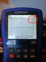
If u zoom in on my photo u will notice when u turn the scope on 2 little arrows automatically line up on the left and right of the horizontal line?? Is this what u mean??
It's only a handheld scope . But what exactly do u mean by align??
If u zoom in on my photo u will notice when u turn the scope on 2 little arrows automatically line up on the left and right of the horizontal line?? Is this what u mean??
Attachments
Last edited:
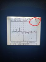
Touch the scope across the terminals of your 12v power supply.
You're responsible for learning to use your equipment. The indicator that you circled may mean that you set the input to ground, not to DC coupling.
You're responsible for learning to use your equipment. The indicator that you circled may mean that you set the input to ground, not to DC coupling.
Fair call. But it's a scope that came with no instructions as I brought it used off eBay mainly to monitor clipping with my subwoofers.
I can not afford to go buy brand new scope with all the bells and instructions . I think by looking at it it automatically alignes (see arrows left and right of horizontal line) ??
I can not afford to go buy brand new scope with all the bells and instructions . I think by looking at it it automatically alignes (see arrows left and right of horizontal line) ??
If DC is an option, why didn't you set it to DC?
Have you searched the net to see if an owner's manual was available?
Have you searched the net to see if an owner's manual was available?

If DC is an option, why didn't you set it to DC?
Have you searched the net to see if an owner's manual was available?
I was confused with what you are saying I appolige. Just get ground reference off main gound input?
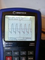
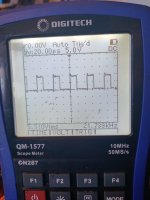
Good bank set on DC
Vs blown bank on DC.
See how the wave is similar to it was on AC that's why I thought using AC was ok.
I would assume the driver is ok and that it's just because no fets are in. Being that the voltage and frequency is the same. If a buffer had gone it would be crazy..would this be semi correct thinking?
Attachments
No sorry I do not have any small caps on hand. I might be able to rustle up a few out of old stuff if it's 100% nessassary? I would assume if u mention it then it would be nessassary. I'll see what I can find. Just one per transformer or would u need 2 because of the NPN and PNP buffers ?
You only need 1. You can move it to the location that you're monitoring with the scope.
Did you mean transformer or transistor?
Did you mean transformer or transistor?
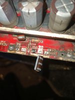
That's not even close to a 0,047uf. It's going to be a film or ceramic capacitor.
Attachments
Last edited:
- Home
- General Interest
- Car Audio
- These class D drive waves look normal??