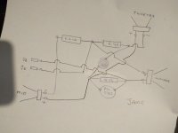
Your drawing was in accordance with your description in post #46. Also, the photos shown do not conflict with it even though we cannot see the drivers themselves.CliffR52 said:Was my drawing accurate and did you find a polarity issue with the current wiring?
Cliffs original drawing is the factory intended way to do this. It does make a difference. Changes should be for a good reason.The coil was in error, the drawing is now corrected.
Attachments
@ Ric
Note that Cliff said 3.3uF capacitor when he listed it, but then showed it as 6.4uF in his schematic.
More confusion!
Note that Cliff said 3.3uF capacitor when he listed it, but then showed it as 6.4uF in his schematic.
More confusion!
Last edited:
@ Cliff.
I would simply short out the protection circuit altogether by soldering a length of wire across the 18R//PTC combination.
The effective removal of the protection circuit will have no significant audible effect in relation to this simple crossover. If you don't believe me, wire 0.8 ohms worth of resistance in place of the protection circuit and do a comparison.
He should be able to by now!Yeah, but I am sure Cliff can work it out.
Thanks for your efforts in redrawing the schematic. 😎
Noted. So, if 0.8 ohm sounds right for the electrolytics, then we may be talking in excess of 0.8 ohm in the case of polyprops.
The proof of the pudding will be in the eating!
The proof of the pudding will be in the eating!
I would NEVER bypass a **tweeter** safety device.
Never.
Minuscule voice coils which won´t come back to life after the proverbial "oops!!!!
Much like the idea of replacing original polyswitches.
Never.
Minuscule voice coils which won´t come back to life after the proverbial "oops!!!!
Much like the idea of replacing original polyswitches.
So do I, JMF.Much like the idea of replacing original polyswitches.
Trouble is, Cliff has been unable to source the exact replacements, as he indicated earlier.
Do you know of an Australian source for the C955 PTC?A visit to Jaycar, they confirmed don't have Thermistors of the correct value.
@ Ric
Note that Cliff said 3.3uF capacitor when he listed it, but then showed it as 6.4uF in his schematic.
More confusion!
Sorry about that.
I'm all over the job.
My mother was hospitalized and not doing too well.
Haven't had a lot of sleep over the last week or two.
It is a 3.3uF capacitor.
I don't know where I got the 6.4
Looks a great source.
I'll check their other products to maximise shipping.
View attachment 845752
Cliff here's another way, preferrable.
If you recommend this crossover layout, I'll go with it.
If the mid and high end up too bright would I add lower value resisters in parallel with the 18 Ohm Resistor (say 1 or 2 ohms) and add until the correct level is achieved?
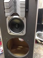
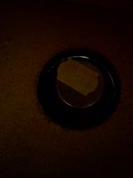
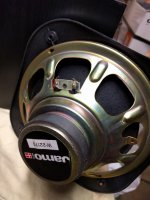
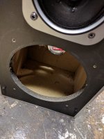
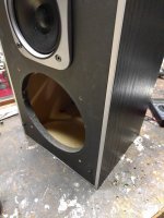
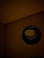
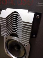
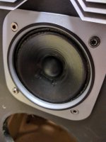
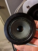
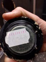
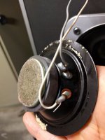
Can you post a photo of the inside of the box looking at the backs of the drivers please?
Attachments
-
 Jamz 10.jpg336.9 KB · Views: 48
 -
 Jamz 9.jpg183.2 KB · Views: 51
 -
 Jamz 8.jpg285.6 KB · Views: 53
 -
 Jamz 7.jpg304.8 KB · Views: 54
 -
 Jamz 6.jpg341.6 KB · Views: 56
 -
 Jamz 5.jpg393.6 KB · Views: 84
 -
 Jamz 4.jpg352.3 KB · Views: 94
 -
 Jamz 1.jpg240 KB · Views: 119
 -
 Jamz 3.jpg367.2 KB · Views: 92
 -
 Jamz 2.jpg317.5 KB · Views: 96
Can you post a photo of the inside of the box looking at the backs of the drivers please?
I posted 2 other replies with photos but I think they may have failed due to upload limit?
This is Cliff's first post can nobody read ?
The decision to eliminate the Thermister was based on previous advice.
The thinking behind it was that a 30 - 40 year old thermister might not be functioning correctly and possibly be compressing the music signal.
If I couldn't source a replacement it was thought it best to eliminate it.
But if a source is readily and cheaply available then I thought it's a good idea to fit a new one. The thinking behind this is, that Thermister might become problematic with time, a brand new one would see me out before starting to play up.
Don't know your thoughts behind the thinking.
Can I still run with your second schematic but just add the thermister in parallel with the 18 ohm resister??
thanks
Cliff
PS: Sorry if there's been rework on your part due to my typos.
Thanks for photos.
View attachment 846007
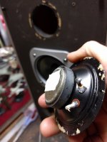
Which terminal is which? and I assume you are counting Red terminals as positive terminals on woofer and mid?
B is the positive.
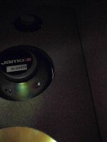
The tweeters (as well as other drivers)are colour coded.
All are marked with a red terminal, which I presume is +ve.
Attachments
Last edited:
Great, thankyou.
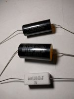
What replacement caps and resistors do you now have, photos please?
Audio grade PP caps.
1 x 2.2 uF
1 x 3.3 uF
Resistor
1 x 18 ohm 5 watt
Attachments
One would have had to read Cliff's previous thread to understand that his decision to remove the PTC was based on an entirely different scenario.This is Cliff's first post can nobody read ?
Simply removing the PTC in the present scenario would leave an 18 ohm resistor in series with the mid/high drivers, not a good idea!
There followed the usual wide ranging discussion! 'Tis the nature of the forum and can be frustrating at times, but we are all friends here. 😎
One would have had to read Cliff's previous thread to understand that his decision to remove the PTC was based on an entirely different scenario.
Simply removing the PTC in the present scenario would leave an 18 ohm resistor in series with the mid/high drivers, not a good idea!
There followed the usual wide ranging discussion! 'Tis the nature of the forum and can be frustrating at times, but we are all friends here. 😎
And the common thing amongst us, the love or attraction to Loudspeakers.
DIY, in my opinion is the way, but to resurrect vintage has the potential of putting a smile on your face for minimal outlay, not to mention going easy on the planet. 🙂

Yes, and this would be the best thing to do now that we have sourced an Australian supplier of the C955 PTC. 🙂Can I still run with ... schematic but just add the thermister in parallel with the 18 ohm resister??
- Home
- Loudspeakers
- Multi-Way
- Thermistor removal from crossover rebuild?