I agree that the schematic isn't correct, but at does suggest that the protection circuit is a C955 PTC in parallel with an 18 ohm resistor.
The combination may be attenuating as well as protecting the squacker/tweeter.
The combination may be attenuating as well as protecting the squacker/tweeter.
Your schematic does not make sense, could you post clear photos of crossover pcb both sides so I can derive the schematic please.
Thanks.
I carefully made note of all the wiring vs driver connections on the Loudspeaker which is still intact.
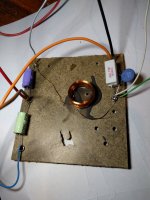
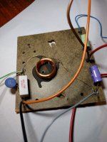
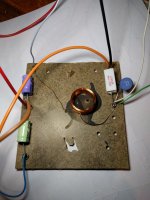
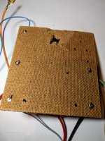
Here are photos of the crossover which was removed from the second cabinet.
Wires:
Binding posts Brown + Caramel -
Woofer Red wire + Black wire -
Tweeter White + Grey -
Mid range Green + Blue -
It is possible that someone has disturbed the polarity by mixing the connections.
Both boxes were wired identically.
Green can is 2.2 μF
Purple can is 3.3 μF
Resistor is 18 Ohm
Blue Thermistor is PTC C995
thanks guys.
Attachments

being a three way and not certain of filter orders changing things, are driver polarities correct?
sorry the schematic is confusing...
Hi turk
Bit of a layman's sketch , but although confusing it exactly follows the physical crossover.
Attachments

I agree that the schematic isn't correct, but at does suggest that the protection circuit is a C955 PTC in parallel with an 18 ohm resistor.
The combination may be attenuating as well as protecting the squacker/tweeter.
Hi.
If it's incorrect, It's possible that someone has terminated the drivers incorrectly.
Both boxes were wired identically.
Do you think I have a polarity issue on my hands?
Let's wait till the schematic is redrawn neatly.Do you think I have a polarity issue on my hands?
P.S. When are you going to measure the resistance of the PTC?
Last edited:
Let's wait till the schematic is redrawn neatly.
P.S. When are you going to measure the resistance of the PTC?
I can give it a go tomorrow after work.
Sorry for the hold up.
Let's wait till the schematic is redrawn neatly.
P.S. When are you going to measure the resistance of the PTC?
Hi.
Before doing the resistance test, I measured 2 newly purchased Resistors to ensure my Tester is accurate.
100 ohm resistor read 100.8 ohms
2 ohm resistor read 2 ohms
After settling down from 1.6 ohms, the C955 PTC Thermistor read 1.3 ohms
Is this what we were looking for?
What resistance does your meter read when you short the probes?1.3 ohms
What resistance does your meter read when you short the probes?
Hi Allen
0.2 ohms
So, the PTC resistance is 1.3 ohm and not the rated resistance of 13 ohm stated on the TDK spec sheet.
That is certainly more in line with the low resistance I expected at the outset of this thread, in fact I expected it to be only a small fraction of an ohm!
This thread has provided a great opportunity to learn more about these devices!
Here's an excellent guide: PTC thermistor - Positive Temperature Coefficient >> Resistor Guide
P.S. Looking forward to Ric's redraw of the crossover circuit. 😎
Thanks
Couldn't have had a more professional appraisal and recommendation.
Blown away.
With these speakers, I'm waiting on the foam surrounds to arrive so I can refoam the Woofers, so I've never listened to them.
Being impatient, on my first restoration (Sound Dynamics) I jumped right in and altered everything without a gradual change.
Your suggestion is far better as it will give me an appreciation of changes with most impact and the subtleties which can be achieved, not to mention backward steps.
I'll also line the boxes with insulation material, something lacking at the moment.
Hopefully I'll be able to get these speakers to a competent enjoyable listening level.
I'll take it all in a number of times to make sure I understand your instructions.
Was my drawing accurate and did you find a polarity issue with the current wiring?
thanks
Cliff
You should subtract this from each resistance measurement you take. Obviously this is only of interest with small values.0.2 ohms
So, the PTC resistance is 1.3 ohm and not the rated resistance of 13 ohm stated on the TDK spec sheet.
That is certainly more in line with the low resistance I expected at the outset of this thread, in fact I expected it to be only a small fraction of an ohm!
This thread has provided a great opportunity to learn more about these devices!
Here's an excellent guide: PTC thermistor - Positive Temperature Coefficient >> Resistor Guide
P.S. Looking forward to Ric's redraw of the crossover circuit. 😎
Thanks G.
I'll make this a reference.
I've always wanted to build a skill around the art of Loudspeakers and privileged to able to draw knowledge from you and others.

Ah! I see from where the confusion has arisen!
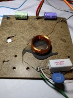
Cliff, in post #1 you said the PTC was a C995, but your photo in post #46 shows it to be a C955! 😱
The C955 has a rated resistance of 0.8 ohms. Phew!
Cliff, in post #1 you said the PTC was a C995, but your photo in post #46 shows it to be a C955! 😱
The C955 has a rated resistance of 0.8 ohms. Phew!
To replace a 0.8 ohms NTC I'd chose an easily to obtain 12 V 18 W car lamp whose cold resistance is about that value and whose filament's thermal capacitance is big enough that it won't be the cause for distortions.
Best regards!
Best regards!
Ah! I see from where the confusion has arisen!
Cliff, in post #1 you said the PTC was a C995, but your photo in post #46 shows it to be a C955! 😱
The C955 has a rated resistance of 0.8 ohms. Phew!
It's age catching up with me.
That and too many projects on the go.
If you add my Tester devices resistance @ 0.2 to 0.3 ohms the C955's 0.8 ohms rating, thats pretty close to 1.3 ohm test result.
lol.
I am curious about mid/tw polarities, they are opposite to what I have seen, wait till you get them going and you can experiment with driver polarity.
After all the recommended changes have been successfully implemented I'll swap the tweeter and mid terminals to listen for changes improvements/degradations incase someone rewired them incorrectly.
When it's finished I'm planning to snip the wire connectors and directly solder to the speaker terminals.
I'd swap the squawker and tweeter connections, 'cause it makes much more sense to feed the tweeter from the smallest capacitor.
Why would you re-connect the choke's negative terminal to the negative input terminal instead of leaving it where it was?
Best regards!
Why would you re-connect the choke's negative terminal to the negative input terminal instead of leaving it where it was?
Best regards!
You may have missed my post while drawing up your schematic, Ric.View attachment 845730The 18R//1R3 PTC combo
We have now established that the rated resistance of the PTC is 0.8 ohm.
25 degrees celcius is the standard measuring temperature for the rated resistance of a PTC.and the PTC is 0R8 at what temperature?
And the transition temperature of the C955 (at which the PTC switches to a rapidly increasing resistance) is around 110 degrees C.
Last edited:
- Home
- Loudspeakers
- Multi-Way
- Thermistor removal from crossover rebuild?