here is the description of the operation of the transformer softstarter.
https://www.fsm.ag/fileadmin/pdf_Da...rzanleitung_Shortinstructions_TSRL_181018.pdf
https://www.fsm.ag/fileadmin/pdf_Da...rzanleitung_Shortinstructions_TSRL_181018.pdf
About 40 years ago a manufacturer of toroidal mains isolating transformers in Auckland NZ was having problems with occasional fuses blowing at turn on, it was determined that residual magnetization in the core, the phase and magnitude at turn on was the problem (baserefex pointed this out). The final and most reliable fix was a low value high power resistor wired in series with the mains input, a suitably rated contactor was wired to short out the resistor, the most interesting part of this story is that a low voltage overwind was placed on the toroidal transformer, this winding went directly to the contactor coil, it seemed the contactors mechanical delay was enough to ensure no fuse failures.

Most are hyper sensitive and trip pretty easily. Where I live we occasionally get those power off-on-off-on over a couple of seconds and this device 100% protects from those events.Does the power dip itself cause the GFI to trip?
Also, the suppressed dynamic voltage available from that overwind may have helped delay the contactor action. There has been recent assessment of in-rush modelling that characterises dynamic inductance influence.the most interesting part of this story is that a low voltage overwind was placed on the toroidal transformer, this winding went directly to the contactor coil, it seemed the contactors mechanical delay was enough to ensure no fuse failures.
It looks to me the best solution is to switch off the transformer into a known low magnetization state, instead of trying to solve the problem at turn-on.
So designing a turnoff circuit that delays the switch-off to secure the magnetization to zero. the capacitor charge up surge needs to be solved separately.
did one for implants: WO2022003162A1 METHOD AND APPARATUS FOR REDUCING THE INRUSH CURRENT OF AN IMPLANTED ELECTRICAL DEVICE
So designing a turnoff circuit that delays the switch-off to secure the magnetization to zero. the capacitor charge up surge needs to be solved separately.
did one for implants: WO2022003162A1 METHOD AND APPARATUS FOR REDUCING THE INRUSH CURRENT OF AN IMPLANTED ELECTRICAL DEVICE
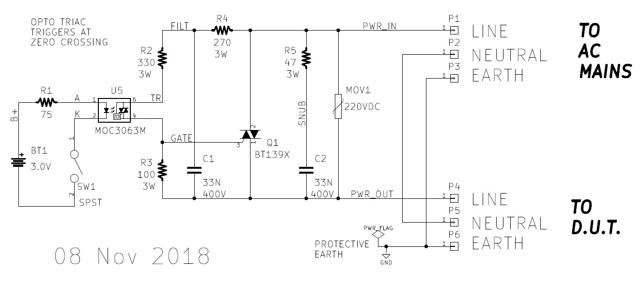
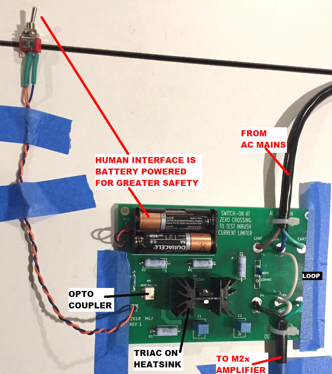
I took a different approach. I built myself a test box which is guaranteed to switch-on the AC mains at the worst possible instant: at the maximum inrush phase of the mains waveform. Namely, at the zero crossing of the voltage sinusoid.
With this gear you simply attach a current sensing scope probe to the AC mains and throw the switch. Presto: you get to measure and to observe exactly how well or exactly how badly, your worst case inrush situation actually is. Here is a (link) to the original discussion, and a few of its photos are shown below.
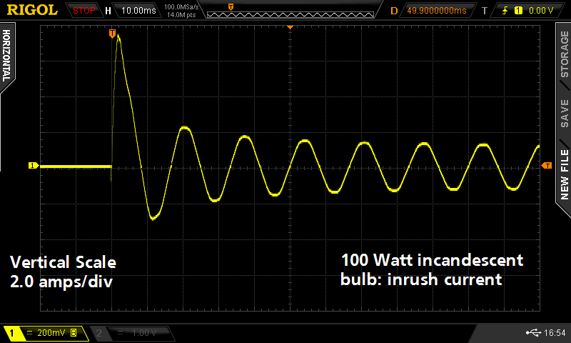
The bottom two pictures attached here show the test box, applying the AC mains to a solid state power amp (Bob Cordell's Super Gain Clone) -- at the worst case zero crossing. This power amp is measured twice: without, and with, "ACPR+SS" ( an AC Power Relay plus Soft Start circuit ). You can see that the soft start has reduced the inrush current from ~24 amperes to ~4.5 amperes. Even when the mains is switched at the worst possible instant: the voltage zero crossing. ELI the ICE man.
_
_
_
_

_

With this gear you simply attach a current sensing scope probe to the AC mains and throw the switch. Presto: you get to measure and to observe exactly how well or exactly how badly, your worst case inrush situation actually is. Here is a (link) to the original discussion, and a few of its photos are shown below.
The bottom two pictures attached here show the test box, applying the AC mains to a solid state power amp (Bob Cordell's Super Gain Clone) -- at the worst case zero crossing. This power amp is measured twice: without, and with, "ACPR+SS" ( an AC Power Relay plus Soft Start circuit ). You can see that the soft start has reduced the inrush current from ~24 amperes to ~4.5 amperes. Even when the mains is switched at the worst possible instant: the voltage zero crossing. ELI the ICE man.
_
_
_
_
_
Oooch! I live close to a 3 phase sub station where the wiring supply impedances and resistances are much lower, and who´s in control when connecting any high VA toroid (at the wrong instance in the cycle) the circuit breaker instantly pops out or repeated anti-surge type fuse blowing.basreflex and others,
With a soft start circuit:
A soft start circuit changes things. Generally . . .
It makes things Better, more complex, more parts, more chance for wiring errors, and more parts to fail.
Without a soft start circuit:
For either a toroid, double C-core, or an E-I power transformer that has a secondary which is loaded by a solid state rectifier (zero warm up time) and the rectifier is loaded by a capacitor input filter . . .
If there is low leakage inductance from the primary to the secondary, then the primary sees a Very Low impedance reflected to the primary when the power is switched on (high inrush current), during the first Alternation that goes from zero crossing to peak voltage (crest).
And, it should be even worse if the switch is closed at the peak voltage (crest).
It makes things less complex, fewer parts, less chance for wiring errors, and fewer parts to fail.
I could be wrong about this; help me to understand if it is different than I just described it.
Comments . . . Please?
Residual Magnetization:
If the toroid core was still magnetized at power down, the issue at the next switch closure would be:
The polarity of the first Alternation, which is Either trying to Increase the residual magnetization in the same direction,
Or, is trying to Decrease the residual magnetization, and then change the direction of the magnetization (more inrush current in this case).
Comments again . . . Please?
Hot Starts:
How does the soft start circuit respond to a hot start?
How does a non-soft start circuit respond to a hot start?
The response of both, may vary.
Just my opinions again
The resistive soft start circuit I posted is only a simplest part-solution but as you rightly point out with a closed iron core, i.e toroid; the magnetic domains can all be pointing the wrong way on power up, hot or cold starts with near zero impedances made worse with cap-input filtering, and it will be the high wattage wirewound ballast resistor that has to absorb the punch. As I see it, there´s no other easy way out of this in-rush game, other than using modest VA rated E&I cores with their inherent lamination gaps.
IAs a traditional tube amper I am horrified at the trend. Interestingly and horribly, I notice many transformer manufacturers are now welding the block of "I´s" on to the block of "E"s; an impossible situation for when it comes to dealing with spewing stray flux..similiar to the DC choke but worse ......
BBaron
I live close to a 3 phase sub station where the wiring supply impedances and resistances are much lower
"Much lower" must be seen in the context of the grid. In my country that would mean a maximum of just 0.28 Ω for a 3 x 25 A service (a typical residential connection). I don't think that it will make much difference for the inrush current of the toroid if your grid connection is 0.05 Ω or 0.25 Ω.
Thanks for all the information, everybody.
I am not going to use a Toroid power transformer.
The E-I power transformers I have, work just fine for all of my applications.
As to spewing magnetic fields: My aluminum chassis; transformer and choke locations and angular orientation; and careful control of input circuit, B+, and other ground loops, even on a small chassis . . . I have less than 100uV hum (OK for my medium efficiency loudspeakers).
Oh, my equipment has lived through many severe Hot Starts (so far).
Even though I use solid state rectifiers.
What is the meaning and result if the power mains is 0.1 Ohms, and the amplifier power transformer primary DCR is 3 Ohms? Your DCR may vary.
3/0.1 = 30:1 . . . The miniature fruit fly in a 3 Pound jar of vegetable cooking grease. It will cook into the meal just fine.
Make life simple, whenever possible.
Just my opinions
Old electronics maxim: If a fuse is put into a circuit in order to protect a transistor . . . the transistor will blow up in order to protect the fuse.
Murphy's Law prevails.
Last edited:
"Much lower" must be seen in the context of the grid. In my country that would mean a maximum of just 0.28 Ω for a 3 x 25 A service (a typical residential connection). I don't think that it will make much difference for the inrush current of the toroid if your grid connection is 0.05 Ω or 0.25 Ω.
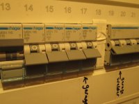
Hold on ! In my rewired house in Germany with 1.35mm dia copper point to point wiring now standard rewiring installation, a 250VA toroid wound for 1.6T on random plug-in will easily trip a 16A B characteristic over-current trip which is fitted as installation standard. The european toaster and kettle both switched on will be on the verge of a 16A B rated trip chattering. Older installations with thicker ring wiring esp. in the UK benefit from vastly increased circuit fuse rating to take all surges, hence protection is often down to the individual UK 13A plug with it´s separate fuse. Modern or rewired housing now requires every layer in the household to be separately fused or relay tripped.
A 20A three phase "C" characteristic trip on the row next to, is for a welding transformer, which specifically makes use of the 1.7T excitation, with power factor capacitance added. A soft inrush on the equipment is still required.
The situation choosing appropriate equipment fuse protection then begins, and in years past, an engineering solution for toroids for studio /audio work is to request the winding house to wind for 1.2 or 1.3T which softens the surge and also reduces the stray magnetic field. That penalty usually results in an increased size and maybe cost. Sadly, those toroid vendors I used have been taken over(or gone bust) but haven´t come across any others who now do this. Majestic transformers (UK) will do this flux reduction with E&I styles only.
As to the diagram with the triac, I wonder how good it really is with that nasty loose connection test, as some years ago I tried a similiar circuit and fused the triac into a short circuit. It requires a very fast reset even on start-ramp up..
BB
Attachments
That second quote is not from one of my posts.
As for the tripping of MCBs or melting of fuses: light devices like consumer amplifiers with - say 300 VA toroids - should not trip a B16 or melt a fast fuse ("gF" IIRC). I have a welder that needs a C16 as it may trip a B16, but that's miles away from an amp.
As for the tripping of MCBs or melting of fuses: light devices like consumer amplifiers with - say 300 VA toroids - should not trip a B16 or melt a fast fuse ("gF" IIRC). I have a welder that needs a C16 as it may trip a B16, but that's miles away from an amp.
Very simple solution to most hot start problems.......Use a line voltage time delay on break commonly found in HVAC units. Lose power you cannot restart the amp for the set amount of time..usually 3 to 5 minutes.
Some of these controls also monitor line voltage.
Some of these controls also monitor line voltage.
How much inrush current?
"All toroids are created equal, but some toroids are more equal than others" . . .
Originally from George Orwell's "Animal Farm" novel; but stolen and highly modified by me.
YMMV
"All toroids are created equal, but some toroids are more equal than others" . . .
Originally from George Orwell's "Animal Farm" novel; but stolen and highly modified by me.
YMMV
The best solution I've found is to short out the thermistor after a few mains cycles. That's enough for it to do its job. I measured hundreds of ampere of inrush current even for remarkable small toroidal transformers. You can see those measurements and read my thoughts here: https://neurochrome.com/pages/the-ultimate-guide-to-soft-start-designI like the thermistor idea and its soft startup. I know a relay could be incorporated, but i like the soft startup of the thermistor. I suppose a Uninterruptible Power Supply (UPS) would solve this. Thoughts on anyone who has had experience with this?
A UPS sounds like a good idea until it runs out of power. Then you're back to square one. So it doesn't really solve anything.
Tom
- Home
- Amplifiers
- Tubes / Valves
- Thermistor protection during brownouts