ugh of course it is. Is 25% of max just a convention? I note that the impedance plot changes with the DC load.
(I had been modelling output impedance slightly differently, adding AC small signal of 1 to current source as a load and plotting Vout/All Loads. Conveniently, then if the only load is the current source of DC = whatever and AC=1 then plotting Vout gives the same answer without having to edit the plot function.*)
* EDIT: then again, my modelled output impedance doesn't change with the addition of the extra J109.
Last edited:
Zout_closed_loop = Zout_open_loop / (1 + loop_gain)
Since Zout_open_loop = (1/gm) and since gm varies with collector current {BJT gm = Ic/(kT/q)}, Zout_closed_loop varies with collector current too. That's one reason why some people "pre-load" their power supplies, to give a guaranteed Ic_min, which gives a guaranteed gm_min, which gives a guaranteed Zout_closed_loop_max.
And oh by the way, since loop_gain varies with frequency, Zout_closed_loop varies with frequency too. This is why higher bandwidth error_amplifiers give lower Zout at high frequencies.
BTW the pure experiment would be to drive your LM329 superzener with an ideal current source (whose Zout is ideal, namely, infinite).
_
Attachments
Last edited:
BTW the pure experiment would be to drive your LM329 superzener with an ideal current source (whose Zout is ideal, namely, infinite).
_
Indeed. The concern I have is that even my model without the pre-regulator - just to take the transient-only LM2941 Spice model out of the equation - is showing no difference in output impedance for each of a resistor , a J109 current source or an ideal current source feeding the LM329... If I probe the cathode of the LM329 there is an improvement of about 7dB at low frequencies from the current source addition (and a dramatic improvement if I assume an ideal current source) but probing Vout has no change.
Last edited:
Looking at the time domain with .tran seems to show no discernible differences as well. Perhaps because the LM329's output is heavily filtered at a corner frequency of 0.22Hz?
If you are interested in the DC output impedance you can temporarily replace all filter capacitors with 0.1pF and run a transient simulation of output current instantaneously switching from 75% Imax to 25% Imax. Let it settle for a few hundred milliseconds and read the value.
The purpose of computer simulation is to correct faulty human intuition.
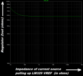
My intuition was faulty; I thought your regulator's output impedance would be sensitive to the impedance of the puller-upper that feeds bias current into the LM329 reference diode. But -- it isn't! Simulation results in Figure 1. I'm guessing that your circuit pulls up the LM329 with an impedance of 1K ohm. Figure 1 shows that pullup impedance makes no difference as long as it's bigger than ~ 100 ohms. Contrary to human intuition!
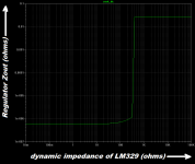
Figure 2 shows what might happen if you were magically able to reach inside the LM329 and change its dynamic output impedance. Answer: in the region where the LM329 operates (0.8 ohms typical, 2.0 ohms datasheet max), not much. A weakness in the simulation harness creates nonsense for dynamic impedances > 200 ohms; the step-up is not real.
Figure 3 varies the DC gain "Avol" of the error amplifier. As expected, closed loop output impedance falls when loop gain rises.
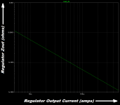
Figure 4 varies the regulator's output current. Since the open loop output impedance is 1/gm and since gm rises when output current rises, human intuition expects closed loop output impedance to fall when output current rises. And fall it does.
_
My intuition was faulty; I thought your regulator's output impedance would be sensitive to the impedance of the puller-upper that feeds bias current into the LM329 reference diode. But -- it isn't! Simulation results in Figure 1. I'm guessing that your circuit pulls up the LM329 with an impedance of 1K ohm. Figure 1 shows that pullup impedance makes no difference as long as it's bigger than ~ 100 ohms. Contrary to human intuition!
Figure 2 shows what might happen if you were magically able to reach inside the LM329 and change its dynamic output impedance. Answer: in the region where the LM329 operates (0.8 ohms typical, 2.0 ohms datasheet max), not much. A weakness in the simulation harness creates nonsense for dynamic impedances > 200 ohms; the step-up is not real.
Figure 3 varies the DC gain "Avol" of the error amplifier. As expected, closed loop output impedance falls when loop gain rises.
Figure 4 varies the regulator's output current. Since the open loop output impedance is 1/gm and since gm rises when output current rises, human intuition expects closed loop output impedance to fall when output current rises. And fall it does.
_
Attachments

FYI: I just bought twenty pieces of these feedthrough capacitors made by TDK: mouser.com link to P/N YFF31HC2A105M
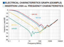
Their DC current rating is 6 amperes, making them attractive for use in medium current and low current power supplies; headphone amps, preamps, etc. They act as a very high quality 1 microfarad capacitor with a self resonant frequency way up at 10+ MHz (!!), figure attached. 1.0uF is bottom curve, labeled "2A105". Put it in a damped RLC lowpass filter and possibly get some very sweet 40dB/decade attenuation of high frequency noise. Might be delightful.
Maybe, insert it after the first R in an RCRC filter between a LM329 zener diode and the VREF input of a voltage regulator's error amplifier. Although John Watson's listening tests in Linear Audio showed approx. zero correlation between regulator noise and subjective listening enjoyment.
_
Attachments
Hi. Sorry for the long delay in replying. I have been focused on trying to get a better measurement setup for my line input board. When I short the pre-amp's input jack (from the outside) I get a noise floor better than -140dBU but as soon as I add a test lead - even a well-shielded one - the best I have been able to achieve is -126dBu. Perhaps not surprising but I was thinking I could achieve better.
I'll take a look at the above. Wasn't it that the tests suggested good line rejection had to be accompanied by low output impedance? I've not read the article. I should track down the back issue.
Taking the family off on holiday for a week and then I will get back to this.
I'll take a look at the above. Wasn't it that the tests suggested good line rejection had to be accompanied by low output impedance? I've not read the article. I should track down the back issue.
Taking the family off on holiday for a week and then I will get back to this.
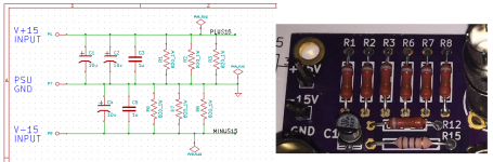
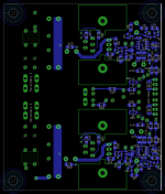
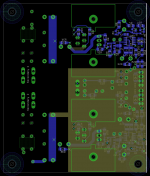
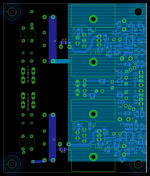
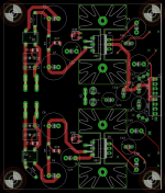
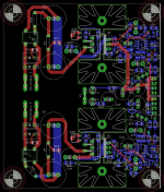
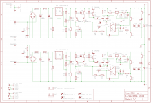
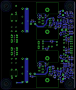
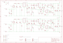
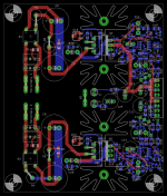
Back at this. I have also made a smaller version without the PCB transformer. Perhaps the overall shape and dimensions could be optimised further but I wasn't keen on having to do the entire right side of the board again. 🙂 I added provision for the EMI filter. Hopefully this is implemented as suggested. I need to work out some component values for bleeder resistors etc.
Pics:
1. Circuit
2. Top and bottom layers
3. Top layer
4. 2nd layer GND plane
5. 3rd layer V- plane
6. Bottom layer
Pics:
1. Circuit
2. Top and bottom layers
3. Top layer
4. 2nd layer GND plane
5. 3rd layer V- plane
6. Bottom layer
Attachments
Last edited:
The TDK YFF3 feedthru capacitor might do an even better job if moved to a position between R13 and C17. The goal is to have a noise free Vref at the opamp input; this new positioning kills both incoming noise and LM329-generated noise. Although John Walton's subjective listening panel found no correlation between power supply measured noise and listening pleasure. (link) Still, as a point of engineering pride if nothing else, why not reduce noise as low as possible? How can it hurt to have lower noise?
_
_
Last edited:

While doing my BoM I noted the AVX tantalum 4.7uF bypass cap has an ESR of 700m Ohms. While I don't have info on the typical ESR of an X7R 0.1uF cap I think I can probably drop R31 and R32.
If you replace them by SMD zero ohm resistors you'll have the flexibility to use different caps with lower ESR if you so choose, on a second build, 9 months from now.
In the schematic of post #175 I got curious about the (Q1 + R18) subcircuit.
So I dug out an MMBFJ108 transistor, soldered some wires to its pins, and connected it up to my resistor substitution box + power supply + milliammeter.
With the supply set to 10.0 volts, I varied the resistance of R18 and recorded the drain current flowing in Q1:
Of course there is unit-to-unit variation from one FET to another, and even more variation between wafer fab lots with different date codes. But some data is better than no data at all, and at least this is some data.
So I dug out an MMBFJ108 transistor, soldered some wires to its pins, and connected it up to my resistor substitution box + power supply + milliammeter.
With the supply set to 10.0 volts, I varied the resistance of R18 and recorded the drain current flowing in Q1:
Code:
    Rsource      Ids
    ===================
     213       15.0 mA
     337       10.0 mA
     459        7.5 mA
     710        5.0 mA
Of course there is unit-to-unit variation from one FET to another, and even more variation between wafer fab lots with different date codes. But some data is better than no data at all, and at least this is some data.
Nice. Thanks. That was next on my To Do list. I was going to wire a 2K trimmer to try to find an optimal resistor value. (I thought you didn't have any MMBFJ108.)
My rather more primitive test setup revealed a value of 453 Ohms for 10mA (happily coinciding with a 1% standard value). 15V supply. I have a modest stock of 10 cut tape MMBFJ108. I don't think I will worry about measuring another sample. 🙂 Those EZ Hook micro clips you suggested I purchase are proving very, very useful.
Last edited:
So purchase sqrt(337*453) = 391 ohm resistors and hope for the best. 390R is the standard value with the greatest number of parts in-stock, on the shelf. It's also the cheapest.
- Status
- Not open for further replies.
- Home
- Amplifiers
- Power Supplies
- Thermal considerations for Fairchild SDIP bridge rectifiers