Hi Gary,
You already paid for shipping on the Korg board. I’ll ship this out today do you don’t have to wait.
You already paid for shipping on the Korg board. I’ll ship this out today do you don’t have to wait.
Hi X,
PSU and motherboard completed, and no smoke! Now it's time to adjust the rail voltages. Im useing 18v tranfos and getting +- 25.9vdc at the DB mounting standoffs on the mother board. I remember reading somewhere in this thread about adjusting for voltage drop, i haven't found it. What should i set the rail voltages at?
Meanie
I found some internal star washers to avoid the issue you had with the DB standoffs. They worked well.
I had the same issue test fitting the vol pot board to the chassis, couldn't thread the pot nut on. Both the header holes and the pot PCB's front edge prevented the pot from seating fully on the front panel. I sanded the pot board, and did some custom bending of the header pins to get things lined up. I used the headers that Vounce had in the original BOM to mount the volume pot board to the motherboard. They have 6mm long pins, and used 20mm standoffs for mounting the motherboard.
I'll post some pics this weekend. Next step is to stuff the Melbs.
Thanks for the reply X, no problem sending the 2 Korg DB's out now by air mail. Appreciate that.
I know others have asked, but any further news on the assembled and tested SSR protection pcb?
I know others have asked, but any further news on the assembled and tested SSR protection pcb?
I just ordered the 2N2007 MOSFETs and 3.3v TO92 voltage regulator. Will build the Korg 6P1 preamp as soon as the parts arrive.
Btw, just saw these handy SE to Bal out THAT1646 converters with breakout board and TRS jack. Looks really handy to have on hand.
https://www.digikey.com/products/en?mpart=BOB-14003&v=1568
Btw, just saw these handy SE to Bal out THAT1646 converters with breakout board and TRS jack. Looks really handy to have on hand.
https://www.digikey.com/products/en?mpart=BOB-14003&v=1568
Last edited:
Yes - all the way to Alaska is a pretty decent trip. I am waiting for my bits and pieces to arrive before building mine.
Just completed my Melbourne Daughter card for the Yarra Preamp.
It works immediately, sings beautifully now. Lucky me didn't make any mistake in soldering.
Currently using +/- 15Vdc rail voltages on Yarra, do i need to set any bias on the Melb DC?
I have not found the proper heatsinks, so now running naked, will this be a problem?
It works immediately, sings beautifully now. Lucky me didn't make any mistake in soldering.
Currently using +/- 15Vdc rail voltages on Yarra, do i need to set any bias on the Melb DC?
I have not found the proper heatsinks, so now running naked, will this be a problem?
Nothing to set as bias is based on resistor values. Should be around 25mA to 45mA depending on your MOSFETs.
15v x 0.025mA is 375mW dissipation in each DN2540 and same in KSA1381. Should be ok without heatsink. But if you run higher rails you may need to use them. Still recommends to use heatsink when you get them. Even the stamped serrated fins are fine.
Great that it plays music. Try driving your M2X or F6 with the Yarra/Melbourne.
Korg 6P1 Preamp for Yarra Verification Build
I finally had some time today to sling some solder and decided to build the Korg 6P1 preamp for the Yarra. It went together easily - only 11 resistors and 11 caps per module - easy to do in a few hours. What took longer was the fact that my Yarra motherboard was only set up for DC-coupled input and output, so I had to install all the coupling caps on input and output. I am using some rare 5uF metalized polycarbonate bypass caps on the output along with the dual back to back 4700uF Nichicons. On the input, I am using the BOM spec'd huge red 10uF Wima MKP's. Also had to add the input RFI filter consisting of 2k2 and 220pF and 100k to ground.
I also adjusted my rails to +29.9v (negative rail not used) as the max allowable voltage on the 3.3v regulators is 30v. I then installed the boards and fired it up. The aqua colored neon glow came on right away to show that it was working. I adjusted the pot to set the bias voltage for the grid (as measured at the top of R113) to be 2.5v (I saw this somewhere in Pete Millet's website). It can work at other voltages and easily set anywhere between 0 and 3.3v. Pot middle position was about 1.65v and that made music too. There is probably an effect on the harmonic distortion profile that could be explored.
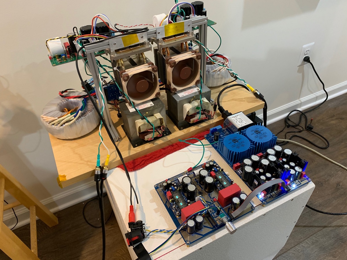
I am using it drive my 50w SE Class Glass Harmony amp (an Aspen commercial design under development still). It actually has quite a bit of gain which is good because the amp is a 0dB gain power stage. Listening to it now and sounds very very good. Will continue to listen and give impressions later.
Main thing is that the preamp works without a hitch - first time. Nice work there by JPS64. I was a bit worried that there woiuld be debugging to do, but works great.
Easy peasy soldering:
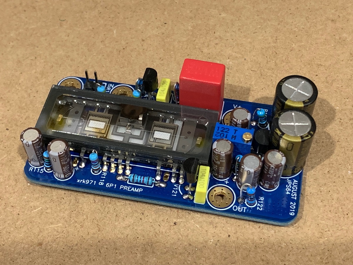
The fluorescent glow lit right up!

Making fine music with Aspen Glass Harmony:
I finally had some time today to sling some solder and decided to build the Korg 6P1 preamp for the Yarra. It went together easily - only 11 resistors and 11 caps per module - easy to do in a few hours. What took longer was the fact that my Yarra motherboard was only set up for DC-coupled input and output, so I had to install all the coupling caps on input and output. I am using some rare 5uF metalized polycarbonate bypass caps on the output along with the dual back to back 4700uF Nichicons. On the input, I am using the BOM spec'd huge red 10uF Wima MKP's. Also had to add the input RFI filter consisting of 2k2 and 220pF and 100k to ground.
I also adjusted my rails to +29.9v (negative rail not used) as the max allowable voltage on the 3.3v regulators is 30v. I then installed the boards and fired it up. The aqua colored neon glow came on right away to show that it was working. I adjusted the pot to set the bias voltage for the grid (as measured at the top of R113) to be 2.5v (I saw this somewhere in Pete Millet's website). It can work at other voltages and easily set anywhere between 0 and 3.3v. Pot middle position was about 1.65v and that made music too. There is probably an effect on the harmonic distortion profile that could be explored.
I am using it drive my 50w SE Class Glass Harmony amp (an Aspen commercial design under development still). It actually has quite a bit of gain which is good because the amp is a 0dB gain power stage. Listening to it now and sounds very very good. Will continue to listen and give impressions later.
Main thing is that the preamp works without a hitch - first time. Nice work there by JPS64. I was a bit worried that there woiuld be debugging to do, but works great.
Easy peasy soldering:
The fluorescent glow lit right up!
Making fine music with Aspen Glass Harmony:
Attachments

Last edited:
Nice work X and JPS64!
Does the polarity at the speakers need to be reversed to retain correct phase?
I believe that is done with NP’s B1Korg, I’m not sure about Pete’s circuit?
Does the polarity at the speakers need to be reversed to retain correct phase?
I believe that is done with NP’s B1Korg, I’m not sure about Pete’s circuit?
It might be a good use of 30 minutes to listen to it both ways, with speaker polarity reversed, and without. If you can hear no difference whatsoever, then conclusion X. If you prefer the sound with speaker polarity not reversed, then conclusion Y. If you prefer the sound with speaker polarity reversed, then conclusion Z.
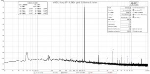
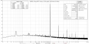
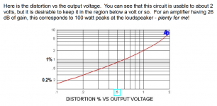
Folks, the grid voltage should be set close to 1.63v to 1.70v - real time FFT's show that it is critical to the nature of the distortion and the level. 2.5v is a terribly high 0.2% THD level. At 1.63 it is about 0.06% and a good balance of 2nd and 3rd and 4th harmonic.
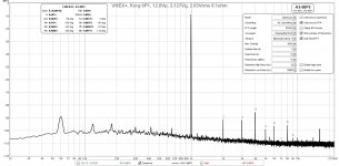
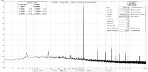
Various grid voltages for 2.83vrms into 8ohms from VHEX+ amp being driven by Korg 6P1.
Various grid voltages for 2.83vrms into 8ohms from VHEX+ amp being driven by Korg 6P1.
Attachments
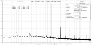
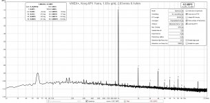

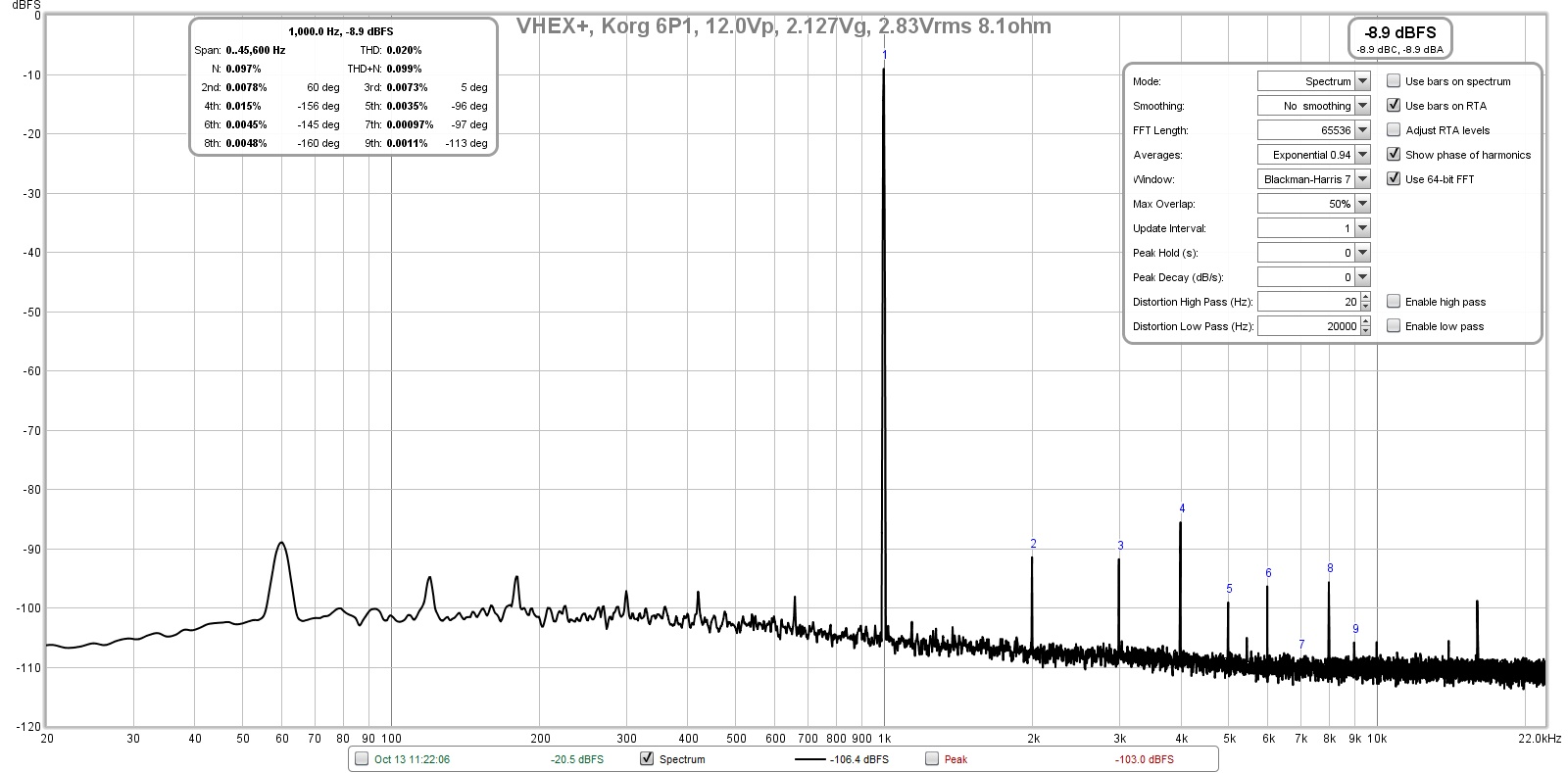
So I tried setting the Korg 6P1 operating setpoints according to the recommended settings shown here, mainly setting the plate voltage to 12.0v (versus setting the grid voltage). Vp can be measured on the left exposed leg of R121, filament voltage (Vf) can be measured at pins 1 or 17 (far left or right) of the 6P1.
So my settings are:
Vp = 12.00v (28.61v upstream of R118 at exposed top leg) and 270kohm plate resistor gives 61.5uA or 31uA each - right within the recommeded plate current.
Vf=0.651v (3.3v uspstream from regulator) and 150R gives 17.7mA, just a tad over the recommended 17mA filament current.
Vg ended up at 2.127v
The resulting harmonic profile has about even amount of H2 and H3 and H4 higher than both. I am not sure what to do to get the 4th order distortion to be lower because the profile needs to be monotonically descending, High 4th order seems to be prevalent.
FFT R122 set at 600ohm:
With R122 set at recommended 1kohm:
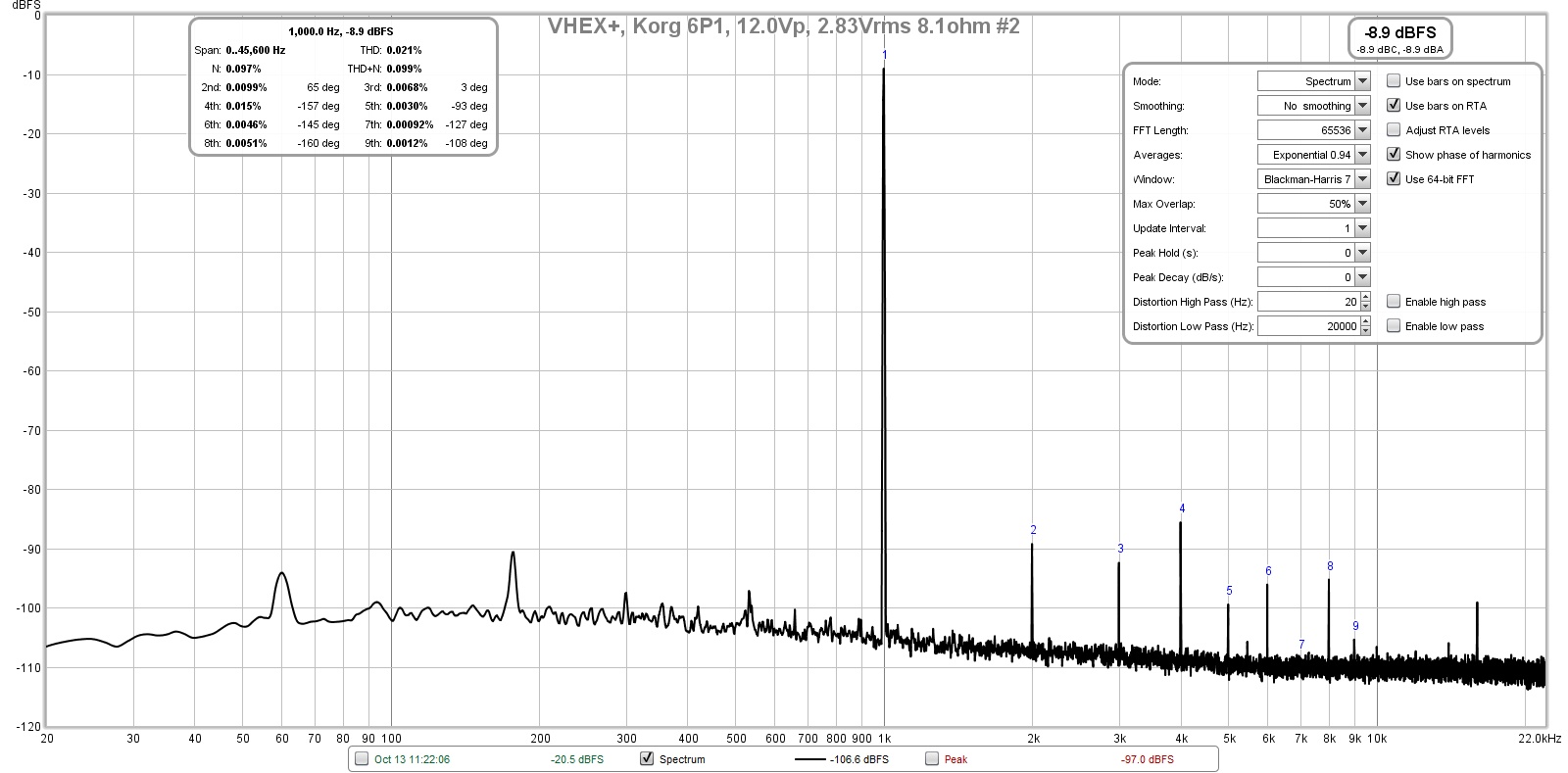
Edit - I kept thinking something is strange with the H4 being high and how there is so much higher order stuff - this should be much cleaner since SE Class A. I removed to the on-board oscillator using the headphone output of the Focusrite and replaced with the Akitika 2ppm 1kHz sine wave oscilator. Finally, things now make sense. We get a dominant 2nd order harmonic distortion and lower 3rd order and nothing else. I will need to look at what is going on with that internal oscillator on the Focusrite. It has not been that far off before.
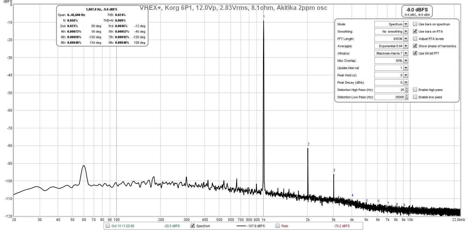
So it looks like the design is good as is, with the requirement that the plate voltage be set at 12.0v per the recommended facotory setting.
So my settings are:
Vp = 12.00v (28.61v upstream of R118 at exposed top leg) and 270kohm plate resistor gives 61.5uA or 31uA each - right within the recommeded plate current.
Vf=0.651v (3.3v uspstream from regulator) and 150R gives 17.7mA, just a tad over the recommended 17mA filament current.
Vg ended up at 2.127v
The resulting harmonic profile has about even amount of H2 and H3 and H4 higher than both. I am not sure what to do to get the 4th order distortion to be lower because the profile needs to be monotonically descending, High 4th order seems to be prevalent.
FFT R122 set at 600ohm:
With R122 set at recommended 1kohm:
Edit - I kept thinking something is strange with the H4 being high and how there is so much higher order stuff - this should be much cleaner since SE Class A. I removed to the on-board oscillator using the headphone output of the Focusrite and replaced with the Akitika 2ppm 1kHz sine wave oscilator. Finally, things now make sense. We get a dominant 2nd order harmonic distortion and lower 3rd order and nothing else. I will need to look at what is going on with that internal oscillator on the Focusrite. It has not been that far off before.
So it looks like the design is good as is, with the requirement that the plate voltage be set at 12.0v per the recommended facotory setting.
Attachments

Last edited:
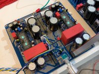
Experimenting my new Yarra/Melbourne setup, was pretty happy that with +/-15Vdc rail, it can drive the M2X Edcor direct effortlessly with and without a 220uF cap.
I actually prefer without the 220uF coupling cap....


I actually prefer without the 220uF coupling cap....
Nice test, Meanie! That RCA it screwed loop crimp connector is pretty cool. Perfect use of it.
Glad it works well.
Glad it works well.
Quick Question. What solder paste should I get for the C116 SDM caps on the Melb DB's? Also, didn't 6L6 make a SDM soldering video? Putting together a mouser order this week, What DB should I build next? I have all of the ones for the Yarra.
That’s just one part - don’t need solder paste. Just use your regular solder. Put a dab of solder on one pad. Put SMT cap on pad and and use metal tweezer tip or a pointy pick to apply downward pressure to hold part in place while you use iron to touch end with solder to melt it. Then touch other end with iron and added solder.
If you use paste - get no-clean flux paste with Pb-Sn. I don’t like Pb free solder as it doesn’t melt smoothly.
The PCA is a great next project. Simple and sounds great.
If you use paste - get no-clean flux paste with Pb-Sn. I don’t like Pb free solder as it doesn’t melt smoothly.
The PCA is a great next project. Simple and sounds great.
- Home
- Group Buys
- The YARRA Preamplifier/HPA for Melbourne DB Group Buy