"having avoided to split of the resonances grounding on the two separate patterns."
Or, having a coherent grounding and coupling of vibrations and resonances along the path from cartridge to platter, rather than gradually increased variation of them through differing paths?
Or, having a coherent grounding and coupling of vibrations and resonances along the path from cartridge to platter, rather than gradually increased variation of them through differing paths?
Quote! but we always hear n' see what we desire to, isn't it?. That's why all that set of mechanical observations/measures... + the near zero play of a single pivoting element?
c
c
Last edited:
Hello warrjon,
"The problem is a servo needs an error"
That part of the sentence should have said: "as far as I know, a servo needs an error."
My tangentially tracking tone arm has a servo and always tracks 100%. There is no "error".
The US Patent Office gave me a Patent on it.
Ralf
"The problem is a servo needs an error"
That part of the sentence should have said: "as far as I know, a servo needs an error."
My tangentially tracking tone arm has a servo and always tracks 100%. There is no "error".
The US Patent Office gave me a Patent on it.
Ralf

Well in reality there is always an error (and noise too). Perfection does not exist in the physical world. Having said that a control system can act to minimize error limited only by the precision you can measure the error and sensor noise levels. The presence of patent is not proof of anything but novelty in the sphere of application relative to the former state of the art...
In the normal sense of the term, a servo requires an error to correct.
In the Ralf arm, the servo seems to adjust the arm to allow the self adjusting head shell
to travel freely within its limited range to minimize the tracking error rather than hit one end of the travel.
That's why some are calling it an antiskating device.
In the Ralf arm, the servo seems to adjust the arm to allow the self adjusting head shell
to travel freely within its limited range to minimize the tracking error rather than hit one end of the travel.
That's why some are calling it an antiskating device.
Since the Linear Tonearms are surely to be included in the Wrong TAs topic (without quotes - front row), here the humble opinion of someone who wasted a lot of time messing with LTAs troubles.
For me Warrion is right, because an error is always necessary to start a servo, and that step is unluckily hundreds of times greater than the movements needed, that I'm trying to obtain with these experiments.
And also Ralf, who brilliantly applied the servo not to the carriage but to the rail, completely bypassing the problem (I think that this is the patent, but there are many other new smart details, such as the reduced offset to use correctly the SD force) is even more right to affirm it.
Your hypothesis is desirable, tonyEE, you just have to design&build it.
carlo


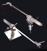
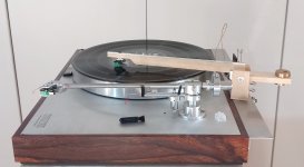
Some time ago, after discussion with Carlo about Cardan arms, I built this one. The cruciform block is the heart of the design. The arm mounted with a high compliance cartridge performs very nicely and was used daily. I also built an experimental model of his 45 degree Cardan proposal, partly because I liked the equal distribution of forces on the bearings including the 50/50 split of the axial and radial loads. I only tested it for freedom of movement and how well it maintained VTF. It passed the VTF test, but I found it visually and tactilely kind of disorienting so I didn't build a working version.
Doug
Not sure why you want a Cardan joint over carefully aligned gimbals. The extra component introduces an extra degree of freedom which means the tube can 'rotate' in addition to move horizontally & vertically.
A unipivot takes this to the extreme and good designs have something to restrict movement to only horizontal & vertical. This was studied extensively in the 60s and you can probably find the articles in HiFi News and Wireless World.
A unipivot takes this to the extreme and good designs have something to restrict movement to only horizontal & vertical. This was studied extensively in the 60s and you can probably find the articles in HiFi News and Wireless World.
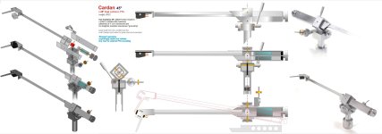
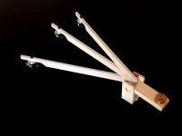
With the Unicardan at hand I started wanting to go deeper.
Observing it carefully the true cardan it's not used at all to transmit the rotation of two non-aligned axes. as Dr. Cardano had thought (note his perplexed face). Blocking instead one of the axes - which in fact is the base - of course blocks the rotation of the other too (so the headshell remains parallel to itself, thanks God... and sorry, kglee) but the arm can go smoothly where it wants regardless of the inclination of the joint. I put it at 45' because it's prettier, but it could be at 19° or at 76° or whatever wanted, it doesn't matter at all.
I made an enlarged mockup to make more precise measurements and better understand a very unintuitive (isn't it?) behavior. the linearity and uniformity of the motion are easily got without problems.
Next the Cardan 45° PTA build - c
last attachment - do not try this at home, but it works flawlessly -
Attachments


Last edited:
"Blocking instead one of the axes - which in fact is the base - of course blocks the rotation of the other too (so the headshell remains parallel to itself)"
So, going back to the input/discussion about good unipivots, this Cardan does what good unipivot designs would do? - in a very simple way.....
How is skating with this?
So, going back to the input/discussion about good unipivots, this Cardan does what good unipivot designs would do? - in a very simple way.....
How is skating with this?
This would require a long answer, partly subjective - I hate to say it sounds like this or that, you know, Mike.-
It's not a unipivot at all, there are still 4 bearings but always loaded uniformly, and this can be heard, imo.
Contrary to what common said, making a correct unipivot, with masses properly aligned is anything but simple (it took me three years of tests and efforts)
.c
it skates like any other decent PTA
I had an SAU2 in 1980 and it was the typical gimballed bearing arrangement, except that rather than having a lateral bearing (usually a shaft in ball races) and a vertical bearing (usually cones in something), it had two bearings, 90 degrees apart, and 45 degrees to horizontal/vertical that were cones in cups (it was a cheap arm, so no budget for ball races). But it meant that an outrigger with adjustable weight could apply bias without friction additional to that caused by the bearing arrangement. Post #16 nicely shows the arrangement.
Although it makes no difference to how the arm works, I'm still unclear as what constitutes a Cardan bearing rather than gimballed. But if you were to use magnetic (frictionless) bearings, this alignment would be ideal. And you really want the bearing axis to be aligned with record surface. Ideally, you'd like centre of gravity there too, but a unipivot needs it a little lower (but only a little).
Although it makes no difference to how the arm works, I'm still unclear as what constitutes a Cardan bearing rather than gimballed. But if you were to use magnetic (frictionless) bearings, this alignment would be ideal. And you really want the bearing axis to be aligned with record surface. Ideally, you'd like centre of gravity there too, but a unipivot needs it a little lower (but only a little).
Last edited:
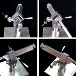
Maybe due to been dealing with it for a while, the difference seems clear to me - #18 attachments
In the gimbals used in the "4 points pivoted" (thorens rega technics and hundreds of other brands, not the first SMEs and others), the wand supports directly the vertical articulation referred to the intermediate ring, which holds the horizontal one referred to the base; let's say it's like the support of a compass, or a gyroscope.
In the Giunto Cardanico (universal joint, how do you call it?) instead, the connection is indirect, through a common rigid cross element, symmetrically referred to both axis - This difference is subtle, but with the first one our cars, the shaft lines of the boats etc. would not work.
From this small difference (which however involves a big design change) I therefore expect a greater motion coherence due to better uniformity of loads on the bearings, and a better resonance grounding due to the simpler path as bonus. The observations and mechanical measurements carried out - Torquemada infamous test included - seem to confirm it, especially when set at 45°.
Is it worth it? as I stated from the first post, as an experiment it is interesting, and able to provide satisfactory results too, at least for me. My opinion is that all the TAs are more or less differently wrong. Strangely these do not seem to be more than others.
carlo
magnetic bearings - frictionless- can you give me some examples? I have always kept away from magnets (foggy reminiscence of Earnshaw?) let alone from de-couplings
the centre of gravity there too, but a unipivot needs it a little lower (but only a little)
Quote! that what took me 3 years, to reduce that distance to minimum, while maitaining the needed stabilty without tricks (damping magnets etc;remedies worse than the issue. imo)
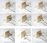
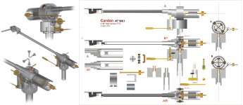
45° Cardan
The design started from a fully turned solution, but then I thought that the 45°Cardan should have a shape showing better his inner "soul".
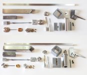
The arm comes out from different alu profiles cut and worked with care. and assembled with epoxy, oven cured + some alu rivets where needed. This in my experience allows lower resonances than machining from solid. The CW is obtained by lead casting - not only heavier, but also much more silent than the usual brass. The few turned elements can be easily replaced by modding commercial pieces.
A few more words on the cardan joint, the key piece of the arm. What is substantial is a perfect alignment - you need adequate equipment or, at least, skill, patience + special jigs. I point out that if in the UniCardan the dimensions are acceptable, here the "cross-piece" has a diameter of just 12 mm and the required precision is relevant. (many different attempts)
The holes, strictly crossing at 90°, must allow some sliding of the pins, but absolutely without any play (crucial!). The axial hole is dedicated to the elastomer to share equally the pressure on pins - i have tried different ones - from the tube of a spray can, Oring neoprene, Delrin, to land on Teflon that shows the right stiffness.
In other fields are commonly used bronze bushings or ball or roller bearings according to the uses, rpm and loads. In our case instead I would avoid the BBs and prefer the pin bearings. I am happy already with cheap pentips on cups (diy modded 2.5 mm SS Allen grains ). but Warren and Mike have built better ones in Carbide for their clever realizations. I would leave the jewells to clock makers, here the loads during the manipulations could be quite expensive.
Here the cross-piece hosts the pentips, while the outer parts the tuning seats, but you could easily do the opposite; even if this would reduce the dimensions - thus increasing the stresses too - in theory could be even stiffer.
c
Warning - all my arms are only prototypes, experiments, even if made by taking advantage of the previous experiences;
What is missing - always thinking it's better to solve the remaining mechanical issues before - are the necessary replications and refinements (materials, details) to reach the best possible solution. This is probably the only true difference between famous TAs sold and our cheap clones.
So take my realization just as a starting point to criticize, there is certainly further room for improvements.
The design started from a fully turned solution, but then I thought that the 45°Cardan should have a shape showing better his inner "soul".
The arm comes out from different alu profiles cut and worked with care. and assembled with epoxy, oven cured + some alu rivets where needed. This in my experience allows lower resonances than machining from solid. The CW is obtained by lead casting - not only heavier, but also much more silent than the usual brass. The few turned elements can be easily replaced by modding commercial pieces.
A few more words on the cardan joint, the key piece of the arm. What is substantial is a perfect alignment - you need adequate equipment or, at least, skill, patience + special jigs. I point out that if in the UniCardan the dimensions are acceptable, here the "cross-piece" has a diameter of just 12 mm and the required precision is relevant. (many different attempts)
The holes, strictly crossing at 90°, must allow some sliding of the pins, but absolutely without any play (crucial!). The axial hole is dedicated to the elastomer to share equally the pressure on pins - i have tried different ones - from the tube of a spray can, Oring neoprene, Delrin, to land on Teflon that shows the right stiffness.
In other fields are commonly used bronze bushings or ball or roller bearings according to the uses, rpm and loads. In our case instead I would avoid the BBs and prefer the pin bearings. I am happy already with cheap pentips on cups (diy modded 2.5 mm SS Allen grains ). but Warren and Mike have built better ones in Carbide for their clever realizations. I would leave the jewells to clock makers, here the loads during the manipulations could be quite expensive.
Here the cross-piece hosts the pentips, while the outer parts the tuning seats, but you could easily do the opposite; even if this would reduce the dimensions - thus increasing the stresses too - in theory could be even stiffer.
c
Warning - all my arms are only prototypes, experiments, even if made by taking advantage of the previous experiences;
What is missing - always thinking it's better to solve the remaining mechanical issues before - are the necessary replications and refinements (materials, details) to reach the best possible solution. This is probably the only true difference between famous TAs sold and our cheap clones.
So take my realization just as a starting point to criticize, there is certainly further room for improvements.
Attachments


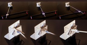
Since already at the beginning I posted their photos, I should conclude with the 2 arms that really deserve the name of Wrong TAs.
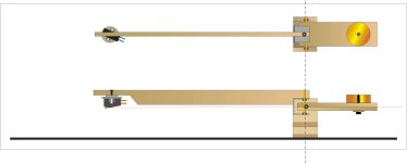
From careful observation of the Unicardan and its axes, came this doubt: what could happen blocking the cross joint and bringing back the TA to a common gimballed, but with the wrong axes?
For a long time i was asking myself whether the behavior of the arms, in addition to the geometry of the forces and the distribution of the masses + frictions etc. was not also due to the overall work, done by the arm during the tracking.
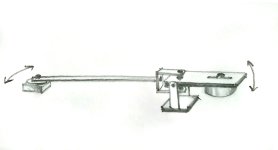
E.g. a pivoted one not only has a favorable lever and not the opposite, but during tracking it also moves the mass of the CW for a few cm, against the >10 cm of a linear. Not only that, but the C.W. is called like this, "Counter Weight", because it is a weight , and the weight force acts only on the vertical, to balance that of the opposite lever. So why move it also horizontally?
This was the first sketch, along with the first doubts shared with two trusted friends (and patients - thanks M+D!)
Of course I had asked myself the problem of the variation of the compliance - vert vs hor - (see calculations) and even more of the variation of the VTF, that is L /L sin alpha (+-10°)? i.e. < 1% during the whole tracking.
A first wooden mockup, built with care, already sounded pretty good if compared with an usual PTA, and this led to the construction of a "normally built" arm, WTA1, and its simplified version, WTA2.
To be continued
c
From careful observation of the Unicardan and its axes, came this doubt: what could happen blocking the cross joint and bringing back the TA to a common gimballed, but with the wrong axes?
For a long time i was asking myself whether the behavior of the arms, in addition to the geometry of the forces and the distribution of the masses + frictions etc. was not also due to the overall work, done by the arm during the tracking.
E.g. a pivoted one not only has a favorable lever and not the opposite, but during tracking it also moves the mass of the CW for a few cm, against the >10 cm of a linear. Not only that, but the C.W. is called like this, "Counter Weight", because it is a weight , and the weight force acts only on the vertical, to balance that of the opposite lever. So why move it also horizontally?
This was the first sketch, along with the first doubts shared with two trusted friends (and patients - thanks M+D!)
Of course I had asked myself the problem of the variation of the compliance - vert vs hor - (see calculations) and even more of the variation of the VTF, that is L /L sin alpha (+-10°)? i.e. < 1% during the whole tracking.
A first wooden mockup, built with care, already sounded pretty good if compared with an usual PTA, and this led to the construction of a "normally built" arm, WTA1, and its simplified version, WTA2.
To be continued
c
Attachments
Last edited:
Would adding to the effective mass be a good thing?- whereas if the stylus doesn't have to move that mass its related distance as it moves across the record it will not suffer the sideload, whichever way it is going at the time, also all the starts and stops with eccentricities.........and the constantly varying sideload involved?
M
M
A construct like this has different effective masses in the horizontal and the vertical plane. When the effective mass is right in the horizontal plane, than it is too much in the vertical plane, lowering the resonance towards rumble or footfalls.
Would adding to the effective mass be a good thing?- whereas if the stylus doesn't have to move that mass its related distance as it moves across the record it will not suffer the sideload, whichever way it is going at the time, also all the starts and stops with eccentricities.........and the constantly varying sideload involved?
M
Mike, this is complex subject and very misunderstood. Effective Mass is NOT mass it's actually inertia and is calculated by the formula I=md^2,
where I = Inertial, m = mass and d^2 = the balance point of the item's distance from the pivot squared.
So EM is m=I/d^2 This calculates the mass at the stylus point. Which again is not actually mass it's force required to commence movement of the arm.
To relate this back to a tonearm. Most pivoting arms have equal or very close to equal EM in both the vertical and horizontal planes. TA's like the Technics that have separate gimbal structures for horizontal and vertical will have different EM, a unipivot will have the same EM.
For decades there has been the thought that the EM of a TA needs to be matched to the cartridge compliance. This is an incorrect way of thinking about what is happening. EM of the arm is ONLY thing holding the cartridge still, if it is too low the cartridge body will move WRT to the stylus (a bad thing).
What is actually required is that EM be high enough to prevent the cart body from being thrown around but low enough so as warps and eccentricity do not deflect the CL. Now eccentricity is 0.55Hz and warp varies but is usually in the 5-7Hz region. This means that a TA with higher horizontal EM so resonance is around 2Hz will hold the body still horizontally allowing better tracking of low frequencies. Then lower vertical EM so resonance is above 8Hz will hold the cart still vertically but allowing the arm to rise and fall quicker so these warps do not cause vertical CL deflection. This is why the carriage @niffy designed is so damn good.
Because it adds to the effective mass. #36
...in fact my thread is called the Wrong Tonearms, but I don't know if anyone noticed that I added the quotation marks:
the "Wrong" Tonearms
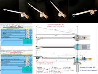
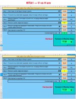
This is because these arms have complex, counterintuitive behaviors, especially for those who already know everything about: eg it is not easy to understand, in theory, that the headshell of the Cardan 45° does not rotate (#29), and that these wrong axis WTAs do not behave like the usual pivoted for which the moment of inertia is calculated.
Here instead is like having two separate entities - the vertical one represented by the entire TA - and the horizontal constituted just by the front part, up to the pivot.
This is why I recommended "see calculations"; the first results with the spreadsheet surprised me so much that I wanted to verify with the dear old formula (were years that i did'nt) (# 35) . It is equally clear that on these H and V EM we can separately intervene as always (mass and distances) for tuning them as needed.
Attached the calculations for the WTA1, where measures were matched as possible.
c
Warren - quote completely your considerations on the so-called "effective mass" (never a name was more misleading), much less on the conclusions, probably just because I have yet to see a cartridge with an inhomogeneous elastomer (cylindrical, prismatic or piano wire). or why the linear carts+CW are so heavy...
More, I'll share with you a doubt: the calculation of the moment is thought for an abstract system, not subject to external fields: we instead use our TAs on our earth. What role does g have on the system?
...in fact my thread is called the Wrong Tonearms, but I don't know if anyone noticed that I added the quotation marks:
the "Wrong" Tonearms
This is because these arms have complex, counterintuitive behaviors, especially for those who already know everything about: eg it is not easy to understand, in theory, that the headshell of the Cardan 45° does not rotate (#29), and that these wrong axis WTAs do not behave like the usual pivoted for which the moment of inertia is calculated.
Here instead is like having two separate entities - the vertical one represented by the entire TA - and the horizontal constituted just by the front part, up to the pivot.
This is why I recommended "see calculations"; the first results with the spreadsheet surprised me so much that I wanted to verify with the dear old formula (were years that i did'nt) (# 35) . It is equally clear that on these H and V EM we can separately intervene as always (mass and distances) for tuning them as needed.
Attached the calculations for the WTA1, where measures were matched as possible.
c
Warren - quote completely your considerations on the so-called "effective mass" (never a name was more misleading), much less on the conclusions, probably just because I have yet to see a cartridge with an inhomogeneous elastomer (cylindrical, prismatic or piano wire). or why the linear carts+CW are so heavy...
More, I'll share with you a doubt: the calculation of the moment is thought for an abstract system, not subject to external fields: we instead use our TAs on our earth. What role does g have on the system?
Attachments
- Home
- Source & Line
- Analogue Source
- the "Wrong" Tonearms