There seems to be a lot of confusion here with the term Effective Mass. As I've said before the term EM is so totally incorrect, what we are actually dealing with is INERTIA either rotational or linear.
In a pivoting arm anything that is moving (pivoting) contributes to the rotational inertia of the body. in a gimbal or unipivot arm the CW moves with the arm wand so it contributes to both vertical and horizontal inertia. Carlo's WTA looks like the CW DOES NOT move with horizontal movement so it contributes NOTHING to horizontal inertia and can be ignored.
Carlo if you want to post all the masses and the centroid measurements I will calculate EM for both H and V
Linear tracking arms that DO NOT pivot like an AIR Bearing or the rail type as in the Linear tracker threaded, H inertia is linear not rotational so the entire mass of the carriage contributes to H EM. Where as V is rotational and follows rules in #60.
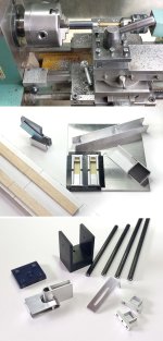
Meanwhile, the last one: a spartan, simplified version of a WTA.
In reality, if the parts are fewer and faster to build, the alignments must be accurate and asks for mounting jigs, and a gadget was also necessary to bend correctly the alu plate for the joints
A clarification - these WTA arms require precise leveling, almost as the linear ones. and not only for the azimuth like any TA, but to avoid variations of VTF during the tracking arc. For this reason in the base there is a simple leveling device wich uses the compression of an O-ring, already tested on my radial RTA and PTTA.
Then a sketch were to put the hands next time, maybe ( F C45 naked)
carlo
Thanks for your help, Warren; I did my calcs (S.S. and hand made ones) imposing zero grams for the CW and zero distance when calculating the H em. Results were more than sufficient to go on with the design procedure, with consistent hints - Some mods, as usual, during the building to put the lead CW even nearer to pivot.
Now i'm making a pair of sketches to answer to Doug from my pragmatic point of view; more than how to (from Anderson / Shure times it should be known), I'm interested in clarifying where (point of application of the moment) and why we have to do those calcs
Attachments


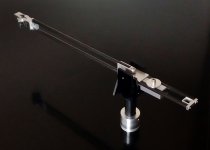

Carlo, in both these fascinating examples of lateral thinking you have used a pair of tubes for the wand, is there a reason why you chose this route other than the suitability to pick up the bearing positions neatly at the pivot end?
Certainly: after an in-depth analysis on the pros & cons of getting the maximum structural continuity between joints and wand, combined with the lightness that only a beam allows, my lateral view discovered in a drawer several 5mm CF tubes, abandoned from the EASY Pi Peucellier linear build..: -)
Ah, of course, a totally logical thought process and brilliant conclusion, I should have thought that through myself.