Sorry ghellman don't mean to be rude or unpolite, but that soldering job is very messy!
There is absolutely no need to use super glue and what not when you follow a few simple rules. There are many tutorials on the net about smd soldering, plus there are postings by numerous people here in Diyaudio.
With a good soldering station set to the correct temperature, a fine tip and good solder (I was using the recommended Cardas solder that melts when you look hard at it) soldering the psu should be very straightforward. For me it worked best to slightly pretin one pad, put the component in place with tweezers and apply solder to the pretinned side. Then turn around and solder the other. Soldering with Cardas solder (or equivalent) is really easy, for the tiny stuff additionally get a Flux pen.
I think OPC gave good advice on soldering in this very thread...
Looks like some cold solder joints on the diodes.
And again not to make you feel bad, but you need to tidy up the soldering. The skewed components are not the end of the world, but there is definitely some cold solder joints, r joints that are not conducting properly there. Caused by either to little heat, or movement of the part after heat has been removed.
What type of solder are you using?
It does make a difference.
I appreciate the help and comments!
(these pictures are actually after I cleaned it up a bit; in cleaning up I tore a lead off of one of the diodes and tried to solder another lead back on - maybe that is a bad idea)
I was encouraged that one side seemed to work (V+)
I will try again - I had tried a little solder paste - but maybe I will try some Cardas solder as you suggested.
Thanks again
Tearing off the diodes lead probably didn't help 🙂 However, just from the pics, one leg of VR2 doesn't look to have been soldered at all and one soldered but not to the board. Double check everything is soldered... miss-aligned components aren't a big issue unless they're shorting out to a neighbour, they just make it a touch harder to solder and look a little untidy.
Can recommend Rosin Flux for use when soldering... makes initial soldering & re-flowing joints much easier. General tip... aim to have each joint done in < 3 seconds.
Hope you get everything running correctly.
Paul
Can recommend Rosin Flux for use when soldering... makes initial soldering & re-flowing joints much easier. General tip... aim to have each joint done in < 3 seconds.
Hope you get everything running correctly.
Paul
I think you are right about the VR - I did have, earlier today, both a positive and a negative VDC - The negative was -19.0 VDC BUT would not "trim down" - so I guess the VR was not really "in the circuit". As I tore into resoldering - I lost one of the 1K resistors (I think a spider ran off with it...)
So I will wait till getting more parts to finish that one.
So then I had another kit of PSU v1 - and just now finished that - I am getting (only?) 6.73VDC and + 6.76 VDC. It does not seem to be able to go higher. This was with an Antek 30VAC transformer.
So another question - Is +- 6.7VDC OK ?
Thanks again
Nevermind - sorry - That transformer is supposed to be 10VAC ( I measured 14VAC) - and the output after PSU v1 was +- 6.5VDC
Thanks
Thanks
14VAC sounds about right without a load... the 10VAC transformer should easily be good for +/- 12VDC with the PSU v1. The +/- 6.5VDC is about the minimum voltage available with the 1K resistor and trimmer pots set to their lowest value [0 Ohm].
Hi.
After looking for information here, I need some confirmations.
I'm building the SE-SE configuration, with the PSU outputing 15V (going to use an Amveco with 15V parallel 30V series 10VA or equivalent, I think).
I want to use a pot to control the volume, probably 20K or 10K (RK27 maybe).
What would I have to change in the board? I read that shosrting R13 and R17, putting a 1M resistor in R14 and R18 and connecting the pot at the input (H something, I haven't received the boards yet) would do the trick.
Also, my source has a 1.4Vrms output, so an unity gain is enough for almost everything, or should I crank the gain to 2x? (Maybe disregard this question, I should buy both pairs of resistors and see this one myself).
Thanks in advance.
Please don't take this as gospel...
Yes, short [0 Ohm jumper] R13 and R17. With a 10K pot, I used a 100K resistor for R14 and R18. Think the recommendation was to use a resistor 10x the value of the pot... 20K - 200K, 50K - 500K, 100K - 1M...
Even with a 1.4Vrms source, unity gain [x1.1] will be enough to power a huge assortment of headphones to well over 100dB. IIRC, my Sennheiser HD650's hit 110dB with 2.2Vrms.
Didn't know the "10x rule" for those resistors, thanks.
Anyway, this time for the PSU (if you used opc's one) is there enough space to put 16mm diameter bulk caps? Pictures of the boards tell me no, but finding 12.5mm 3300uF caps is hard, unless you buy those run-of-the-mill ones.
Anyway, this time for the PSU (if you used opc's one) is there enough space to put 16mm diameter bulk caps? Pictures of the boards tell me no, but finding 12.5mm 3300uF caps is hard, unless you buy those run-of-the-mill ones.
This is for 'The Wire' PSU v2, C16, C19, C51 and C67... a 16mm cap definitely wont fit, there's only ~1mm gap with the 12.5 caps. I used the same caps as listed in the BOM but rated at 2700uF... Digikey has the correct 3300uF caps in stock. If you hunt back through the thread, there were a few other alternatives mentioned.
Last edited:
Might have missed that information in the middle of all this pages.
I'll probably go with 2700uF ones, I'm buying through Mouser, I can get stuff there much more cheaper.
I'll probably go with 2700uF ones, I'm buying through Mouser, I can get stuff there much more cheaper.
almost -
I got the power supply (PSUv1 - #2) to supply +-12VDC. The SE-SE works in one channel - but the other just has a low "hum".
I even tried some Bruce Cockburn on it 🙂 - but still just one channel.
Based on my soldering skills, I need to at least touch up the bad side. Hopefully, I did not overheat anything. I will try to take pictures if the touch up does not work.
Thanks
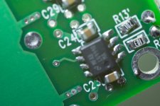
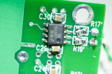
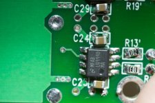
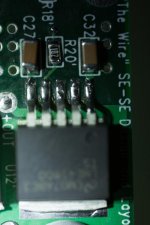
SE-SE one side silent
Please let me know if you see anything. One side works (sounds good!). My test is just to touch the headphone leads to the +OUT and G. (You can get new cables for HD800s - right? 🙂)
U10/R14 (C24 other side) - works
U12/R20 (C30 other side) - no sound -
These pictures show more than I can normally see - maybe just R17 and R19 need to be straightened out?
Thanks for any help or suggestions!
Attachments
-
 IMG_1800.jpg79.1 KB · Views: 501
 -
 IMG_1801.jpg88 KB · Views: 429
 -
 IMG_1803.jpg82.1 KB · Views: 417
 -
 IMG_1804.jpg72.2 KB · Views: 418
 -
 IMG_1809.jpg69.4 KB · Views: 415
 -
 IMG_1811.jpg80.2 KB · Views: 217
 -
 IMG_1813.jpg78.9 KB · Views: 198
 -
 IMG_1814.jpg66.9 KB · Views: 188
 -
 IMG_1816.jpg59.5 KB · Views: 199
Better, as I see no grey soldering. Grey is not the colour you want. You want nice a shiny. Next up. A good solder job will leave the solder nicely sucked into the component in a clean fillet between the component pads and the pads on the PCB.
Some of your components are way to crooked to leave be.
R13 and R17 especially.
Last tap on the opamp, beside the SE-SE designation may be suspect as well.
If you have a magnifier , well it is your best friend. One of those that has a light and an arm to hold it is my best friend. When things get smaller yet I have a surface mount stereo microscope I picked up real cheap.
O think you have enough solder on most of the tabs. A reheat and a position with a toothpic to hold them in place while the solder sets may be all that you need.
It is definitely looking better.
And you have one channel running.
Plus you have probably deduced correctly that you were not regulating the output in one of the boards. Progress!
And light at the end of the tunnel.
TUnes.... Glorious tunes!
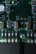
Agreed with Mark, and to add, the top side of R16 in picture two looks like it hasn't been soldered correctly. The solder may be stuck to the pad, but it doesn't appear to have flowed onto the resistor.
In pictures 3 and 4, the GND lead on the large poly caps also looks like it hasn't been soldered.
Good news is that all the ICs look pretty good, but the passive parts need to be re-aligned. Some are unacceptably crooked.
Based on the pictures, I'd say you're not getting enough heat onto any of the joints, so either turn the iron up, use a larger chisel tip, or take a little longer on each joint. The solder should flow freely and set to a nice shiny finish as Mark suggested. Also, if you're using lead free solder, go get some leaded stuff. Not so great for the health, but much better for the solder joints.
Cheers,
Owen
I suspect some of the wires to have poor connections. Make sure you're heating both the pad as well as the part you are soldering to it, or you won't get a proper connection.
Hi all. I have a couple of questions re putting together my wire se-se and was hoping one or more of you might be able to weigh in.
1) After completing the surface mount work on my psu board, I realized that I used the 1uf ceramic caps from the se-se bom instead of the ones specified on the psu bom. These caps appear to have identical base specs, power handling, tolerance etc. Is there any reason I shouldn't proceed and use the ones on the psu bom on my amp board?
2) I've built a couple of bottlehead kits, a mini3 and an o2, but this is my first big boy project requiring real case work - and I don't really have the tools for it. Is there a precut chassis on ebay or elsewhere that any of you can recommend? For reference, I am using the amveco transformer recommended earlier in the thread. Thanks!
Hello, I just received the boards today, and surprisingly found they are V2. Never noticed such a version existed. And I think the wiki is not updated on this.
I see the SE-SE V2 mostly identical to original version. So nothing much here.
The major question is, where is the trimmer position on the PSU V2? Besides the Q3B and Q4B pins, there are a pair of 4 pin-holes, what are they for? Protection diode pads missing? Are they still configured for LM317/337? I think I must have missed something. Please educate me on this.
I would totally complain about this PSU V2 layout. The input/output caps spaces are enlarged, rectifier spaces are larger. Anything (calculation/measurements?) justifies the choice? probaly due to peer pressure? The advantage might be using the 2700uf cap rated 25V and higher speced rectifiers? With such a highly integrated and efficient circuit, nothing power hungry would exist at all. I believe on the output side 20V 560uF os-con would have already been a super overkill (if you do want to fry the thing with +/- 20V), considering that anything beyond 10uF would have no really significant effect according to TI's LM317 manual. Ok, peace about it, though I have bought the components according to BOM V1.
And now the PSU board is not the same width as the amp board, and mounting holes do not align (maybe now the PSU V2 align with BAL-BAL?). Also the board length increases quite a bit. Not a very smart way to go. Now, anywhere I can find the dimensions of the new V2 PSU and SE-SE? I am working on a CAD design for the whole chasis layout.
And the last thing, white board is neither beautiful (personal opinion) nor easy for route checking. And, if you measure temperature with infrared guns/cameras, it messes things up. At least you would have to set dramatically different emissivity for the board/parts.
At this moment, I feel like willing to exchange this V2 PSU with a V1 board, if anyone offers (in US) and favors the larger cap space on V2.
Sorry for being bit of aggressive about it.
- Home
- Amplifiers
- Headphone Systems
- "The Wire" Ultra-High Performance Headphone Amplifier - PCB's