Almost like a Karaoke filter when you remove the voice...
If it is single-ended that is what happens when the ground is missing on the input wiring, like opc says. Check your grounding on both ends of the cable. The same exact thing has happened with the O2 headamp before.
Last edited:
This is what i thought having encountered a similar issue some time ago but my input ground seems to be ok. I'll double check the soldering for cold solder joint.
Thanks
Do
Thanks
Do
Ok, so before re-touching anything I checked every connections against the schematics and everything matches, only seems to be a type on the schematics about C23-C24 which are reversed fin pinout and same for C29-C30 but this is no issue.
Decided to connect everything to my computer sound card line out and it is working perfectly... Only when I add a pot in front of the line-in it seems to mess things... Pot is wired properly and even plugged in my LDR3x and same issue.
I have not re-tested since I tried on the computer so I will do this. I mean, this is really simple schematics and I don't know where I could get it wrong... 😀
Ciao!
Do
Ok, all good now... Must have been me inverting GND and signal position on the line-in connectors, nothing else since I tripple check everything all the time before and after... Yeah I'm that parano... 😀
Sounds really nice btw! Thanks for this nice project Owen!
Just a little question and you can answer me by PM if you prefer but I have a NTD1 V2 (second batch) and wanted to know if V3 will be a huge improvement in SQ over the one I have and it can justify assembling the new one cost wise?
Ciao!
Do
Sounds really nice btw! Thanks for this nice project Owen!
Just a little question and you can answer me by PM if you prefer but I have a NTD1 V2 (second batch) and wanted to know if V3 will be a huge improvement in SQ over the one I have and it can justify assembling the new one cost wise?
Ciao!
Do
Go here to the 1st page entry #1. http://www.diyaudio.com/forums/vend...jects-available-here-bal-bal-se-se-lpuhp.htmlHi Guys
Is there any option to get a bal-bal pcb ?
Thanks
Karoly
Go here to the 1st page entry #1. http://www.diyaudio.com/forums/vend...jects-available-here-bal-bal-se-se-lpuhp.html
Thanks

1: Is there component kits for the PSU V2?
2: I suppose I can use it as Bal-Se also?
//
2: I suppose I can use it as Bal-Se also?
//
Last edited:
1: Is there component kits for the PSU V2?
2: I suppose I can use it as Bal-Se also?
//
1. No... no parts kits this time. I was hoping someone would organize one, but it never materialized.
2. Yes... The BAL-BAL can also be BAL-SE or SE-BAL, hence the elimination of the older BAL-SE version 🙂
Cheers,
Owen
1. No... no parts kits this time. I was hoping someone would organize one, but it never materialized.
Hi Owen,
I considered organising something but when I do the sums on getting volumes of this gear adequate to make it worthwhile I end up with import duties and taxes into Aus that wipe most of the possible benefits, and that makes it hard for me to justify the investment of my 'spare' time.
Cheers,
Chris
OK OPC, roger that Chris - thanks for consider it!
Owen, I filled in the google chart for boards. How to proceed?
In-impedance... I would like to end up on say 20-30k. How is this achieved? Is there any tradeoff to raise it?
//
Owen, I filled in the google chart for boards. How to proceed?
In-impedance... I would like to end up on say 20-30k. How is this achieved? Is there any tradeoff to raise it?
//
To Troubleshoot PSU (v1)
Hello
first smd project
First tried PSU v1 (had kit sitting for a while)
The positive side is around 15VDC but the negative side .... (0.5V ) I think
I can get a picture soon if that could help.
Are there any "flowchart" for trouble shooting PSU that you all might know of. (That is not for PC power supplies)?
I will start with schematic - I guess look around the LM337T
Do I need to remove components from the circuit?
Thanks for any help or suggestions
First Power down.
Second build a mains bulb tester.
Third test the wiring of the transformer alone. NOTHING on the secondaries.
Second build a mains bulb tester.
Third test the wiring of the transformer alone. NOTHING on the secondaries.
Hi ghellman,
Andrew is correct, and you should probably test the transformer alone to rule out a serious problem. Please be cautions while doing this!
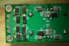
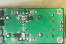
Next up, we would need good pictures of both the top and bottom. There might be a short or a cold joint somewhere and that might help us find it.
If we still cannot see anything, I will need to ask you to measure the voltage at a few points on the board so we can narrow down the possibilities.
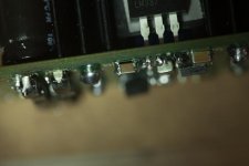
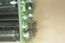
As an obvious test, can you make sure both regulators are properly isolated from the heatsinks by measuring the resistance between the tab of the reg, and the heatsink itself? Use the solder points for the heatsink as the black anodized surface is generally non-conductive.
Cheers,
Owen
Andrew is correct, and you should probably test the transformer alone to rule out a serious problem. Please be cautions while doing this!
Next up, we would need good pictures of both the top and bottom. There might be a short or a cold joint somewhere and that might help us find it.
If we still cannot see anything, I will need to ask you to measure the voltage at a few points on the board so we can narrow down the possibilities.
As an obvious test, can you make sure both regulators are properly isolated from the heatsinks by measuring the resistance between the tab of the reg, and the heatsink itself? Use the solder points for the heatsink as the black anodized surface is generally non-conductive.
Cheers,
Owen
Just to be sure:
I want to build a BAL-SE. So I get a BAL-BAL board and BAL-SE BOM and follow the assy intersection wiki for BAL-SE?
//
I want to build a BAL-SE. So I get a BAL-BAL board and BAL-SE BOM and follow the assy intersection wiki for BAL-SE?
//
Just to be sure:
I want to build a BAL-SE. So I get a BAL-BAL board and BAL-SE BOM and follow the assy intersection wiki for BAL-SE?
//
No no no!
Get the BAL-BAL, build it up exactly as per the BAL-BAL BOM, and the only thing that needs to change is the way you wire the inputs and outputs.
The inputs are wired as balanced inputs using XLR (or whatever else you might want) and the only difference is that instead of taking the output from + terminal to - terminal, you instead take the output from + terminal and run it back to GND at the PSU input on the BAL-BAL board. This allows to you to use the board with SE output, and also allows you to swap back to differential output if you ever feel the need. You could even wire it up with both a balanced jack, and a 3-pin SE jack and just use one or the other. Alternatively, you can have a pair of 3-pin jacks, and wire one up from the + terminals to GND, and the other from the -terminals to GND to get an inverted and non-inverted output.
Have fun!
Owen
Hi ghellman,
Andrew is correct, and you should probably test the transformer alone to rule out a serious problem. Please be cautions while doing this!
Next up, we would need good pictures of both the top and bottom. There might be a short or a cold joint somewhere and that might help us find it.
If we still cannot see anything, I will need to ask you to measure the voltage at a few points on the board so we can narrow down the possibilities.
As an obvious test, can you make sure both regulators are properly isolated from the heatsinks by measuring the resistance between the tab of the reg, and the heatsink itself? Use the solder points for the heatsink as the black anodized surface is generally non-conductive.
Cheers,
Owen
the resistance between solder points and tab:
317 : 2.8K ohm
337 : 0 ohm
at PSU output:
The 317 (V+) : 5.12 VDC
337 (V-) ... 0.06 vdc
The transformer (antek110) gives 14.65.VAC and 14.69VAC at secondaries
I know (at least) the outside of D10 (topside on #1 pic) is messed up - I tried to resolder the lead.
Attachments
- Home
- Amplifiers
- Headphone Systems
- "The Wire" Ultra-High Performance Headphone Amplifier - PCB's