OPC, in the first post you mention that the complete package with standard transformer mounted measures 1.8" high, is this including the standoffs that you had on at the time?
I'm trying to determine internal dimensions necessary for an enclosure. I'm pretty tight for height on an extruded alu enclosure option that I am thinking about having only 46.9mm internally.
If that 1.8" dimension includes standoff then I may JUST make it (~1mm tolerance though) but with the known risk that a custom transformer in the GB is taller than the transformer specced in the BOM.
With the idea of having a heatsink/aluminium plate attached to underside of the pcb, how thick would that need to be? Would say 4 or 5mm be sufficient thickness?
I am interested in the heat sink option and watch the development.
I must ask: would it be as effective to provide 2 strips of heat transfer (in lieu of the all-machined heat sink) so that any suitable sized flat back heatsink may be used?
I'm aware this requires the addition of another heat transfer interface...but how much heat are we talking about?
I must ask: would it be as effective to provide 2 strips of heat transfer (in lieu of the all-machined heat sink) so that any suitable sized flat back heatsink may be used?
I'm aware this requires the addition of another heat transfer interface...but how much heat are we talking about?
the epoxy packages do not carry much of the heat, you should find a way to couple to the top side of the PCB in some way IMO
hochopeper, i think we have a solution to the case thingo, shoot me an email before going much further with your research
hochopeper, i think we have a solution to the case thingo, shoot me an email before going much further with your research
Ok, I spent 2 afternoons and built 1 amp already. Am having a bit of difficulty debugging some issues. The sound is coming through but is very low in volume and full of static. I'm using an integra dtc 9.8 for the balanced out and a 240R for the R3.
DC voltage on the transformer is around 21V with 115 AC in.
Also some direction on adjusting the bias would be immensely helpful.
Thanks,
Tom.
DC voltage on the transformer is around 21V with 115 AC in.
Also some direction on adjusting the bias would be immensely helpful.
Thanks,
Tom.
There is no bias... you don't get much more plug and play than this.
I built my remaining 4 amps over the weekend, and all 4 of them powered up and worked perfectly the first time. Two SE and two BAL inputs, both set for 15dB.
I've also tested the higher gain setting and it works perfectly as well.
If you're getting low output and fuzz, something is seriously wrong. Can you post pictures? What do you have the output of the regs set to? Hopefully not 21VDC or the input op-amps will probably be dead.
We'll need more details or it's going to be tough to help out. If I were you, I would avoid powering this up until we have a better look.
Regards,
Owen
Attachments
adjusting the bias? DC on the TX? you mean AC? this would give you ~28-29 after the diode drop, this is perhaps a bit too high for the caps and the sinks in the psu BOM.
We have never had a bias adjustment procedure for the wire bal-se amps that this is based on, the opamps in the input stage dont need bias adjustment, in fact most modern opamps of this caliber operate mostly in class A in these loading conditions on their own and the buffers definitely so. there is no facility to adjust the bias, do you mean adjusting the Vout of the regulators? those are the only pots on the board.
you really shouldnt be running speakers until you have verified the correct operation of the amp as its DC coupled. what DC voltage to you have from:
the DC voltage before and after the regulators to G
the output of your source from each +/- to G?
the output of the amp with no speaker connected
what voltages do you have from pin 4 (the neg power pin) and pin 7 (the pos power pin) on the lme49990 to ground. definitely leave this till last, it probably wont be needed and must be done very carefully, they should all be equal to the output if the regs anyway
also some pics will help immensely
edit: haha i see opc beat me to it. hes probably right about not powering it up till we've worked out exactly what you have done
Last edited:
I presume by bias he means the regulator pots, in which case he hasnt followed standard procedure by building the regulator first and testing, setting output voltage before stuffing the amp section. or set the voltage at all
Correct, I meant to say the regulator pots. No, I didn't adjust them.
Where should this be measured at? I measured 21vdc at the diodes.
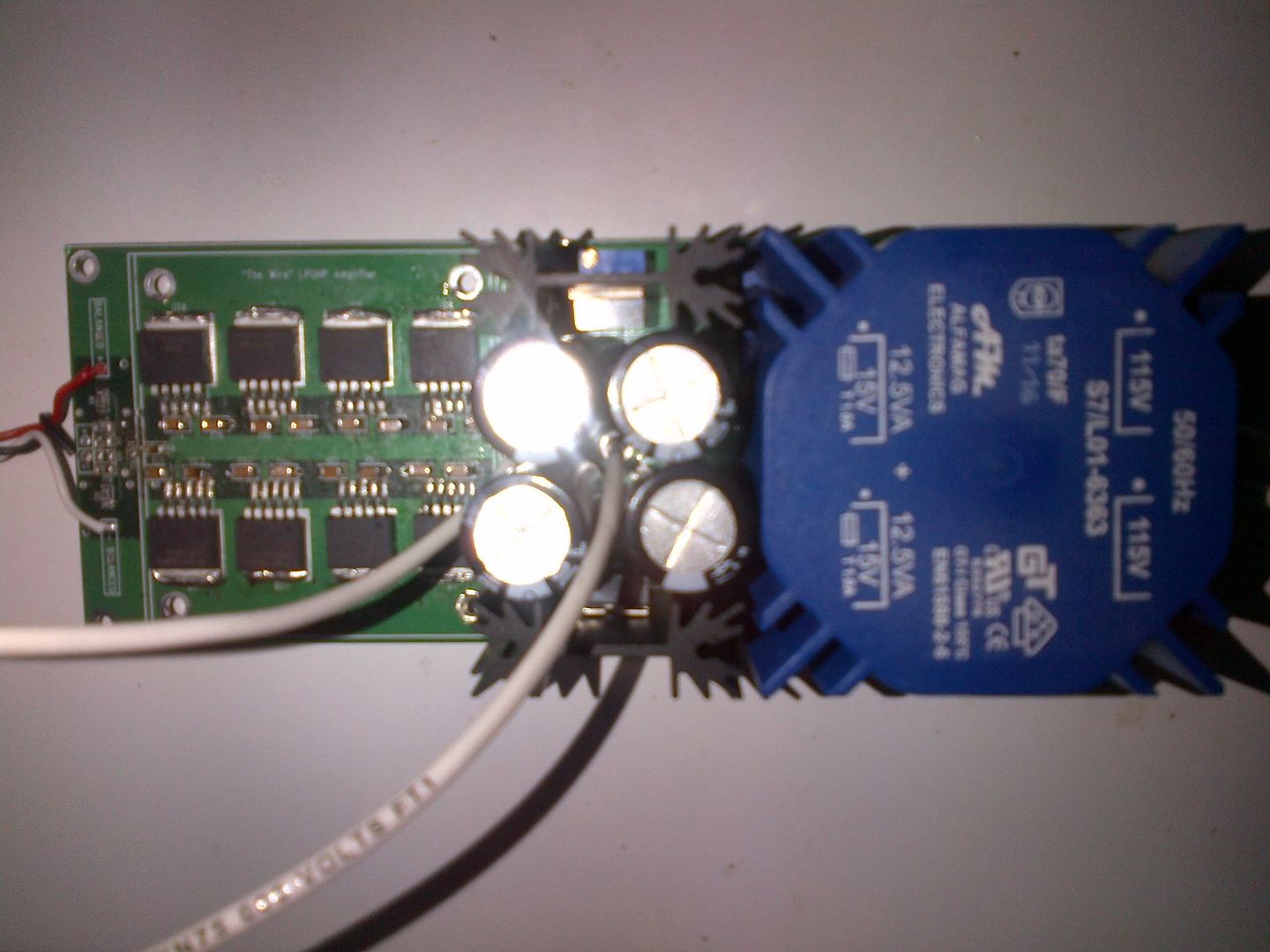
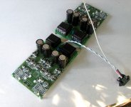
Here's a pic of the top and bottom of the pcb:

T.
Where should this be measured at? I measured 21vdc at the diodes.
Here's a pic of the top and bottom of the pcb:
T.
something marginally in focus would be better 🙂 , i cannot see anything. also best to adjust the size of the pics too so they arent so huge
i fear you have already killed the amp if you had those voltages anywhere after the regs, i have given you the info to test, please follow that and also get us some new pics =P
first of all, turn all the reg pots down all the way till you feel a bit of resistance, then just find somewhere suitable at the output of the reg like C95 and C96 and adjust the output with the pots till you get +15->17v and -15->17v
"Down" in this case being fully CCW?
hmm i hadnt looked to check orientation, but most likely yes, i think i remember opc mentioning that in his little instruction on this and thats how it is on the PSU boards. it will still be sitting at about 14-15vdc at this stage, the pot just adjusts the final bit
opc can probably confirm the orientation of the pots does indeed mean CCW to turn down. i dont think he should be turning it on at all until we have better pics anyway, but most definitely without the voltage setup correctly there could be all manner of problems, or it could just have the rails so far out of whack that hes got some sort of asymmetrical clipping going on.
i just hope the board isnt dead, because unless the pots were turned mostly down on arrival we have the 14-15vdc set by the SMD 240R and 2k0 on the board, plus another 15 or so volts of adjustment on the pot till the reg cant give anymore. minimum dropout will be about 1.5-2v under load i would think, so we could have 18-19v into the opamps without much trouble
luckily these chips have proven to be pretty hardy lately, surprisingly so; so if we can get the voltage right theres a good change it'll be fine
Last edited:
OK i'm going to start a build thread now with a couple of important notes for construction. it really should be in the chipamp forum shouldnt it? i mean sure its solid state as well. should i just keep it here since the GB thread was here so its easier to find?
the first post will be very brief at this stage and i'll add to it, particularly more once i have the boards, but i think its important to have the stuffing and intial setup, which is pretty straight forward, stuff regs first, test, set voltage, stuff the amp section and readjust. test DC at output and input before attaching your source, attach source, readjust if needed and off you go
the first post will be very brief at this stage and i'll add to it, particularly more once i have the boards, but i think its important to have the stuffing and intial setup, which is pretty straight forward, stuff regs first, test, set voltage, stuff the amp section and readjust. test DC at output and input before attaching your source, attach source, readjust if needed and off you go
hmm... I wasn't going to do a build wiki for this one as I assumed it was a pretty straightforward build, and was mostly targeted to advanced builders.
I see a few issues off-hand:
1. It doesn't look like the regs are mounted correctly to the heatsinks, and I don't see any type of isolation pads used. If that's the case, then the tab on the regs is being shorted to ground and one or both of the rails could be shorted after the regs.
2. Always build the PSU first, and adjust the pots all the way down (I can confirm that this is CCW on these boards). Bring the rails up to 18VDC by adjusting the pots CW and then power down, drain the caps and proceed with the rest of of the build.
We need some better pictures of the front end, both top and bottom. It looks like one of the caps is crooked and could be shorting.
If one of your rails was shorted out, then that might explain the low level fuzzy sounding audio. Check for continuity between the tabs and the heatsink. If you measure low impedance then this is bad, and you've found your problem.
Once you've isolated those guys, and confirmed the orientation of the op-amps in the front end, then turn the pots for the PSU voltage all the way down and plug the unit in. Adjust the voltage to +/-15V to start and then we can continue troubleshooting if that doesn't work.
Regards,
Owen
Last edited:
no need for a build wiki, just a dedicated build thread with the contents of your above post spelled out. even with advanced builders who may not need the build instructions per-say, its still good to have a dedicated thread where build/casework issues and smd tips etc can be discussed, plus its a celebration of the beginning of the project proper. basically anyone that needed a build wiki can just reference the bal-se headamp for the majority. many may be advanced builders (clearly not all) but never done much SMD so I expect there will be a few queries related to that.
Last edited:
I built my remaining 4 amps over the weekend, and all 4 of them powered up and worked perfectly the first time. Two SE and two BAL inputs, both set for 15dB.
I've also tested the higher gain setting and it works perfectly as well.
Those are some handsome amplifiers you've got there Owen!
That photo makes my soldering hand itchy ...
Does anyone object to my categorising the LPUHP as a 'miniblock' rather than 'monoblock'?
Perhaps Ed might? 😛
Last edited:
I like "miniblock"...The thought bubbles which portray the inner workings of your minds continue to merit my scrutiny... where's the freakin' smiley face?Perhaps Ed might? 😛
That photo makes my soldering hand hurt! It took me 8 hours total to go from start to finish for the 4 units, and I think I worked it out to be 840 solder joints total.
Not bad for a complete pair of amps, but definitely a good amount of work!
I've attached a picture of how the regs need to be mounted to the heatsinks. you'll need a thermal pad and an islolating shoulder washer to prevent the screw from shorting the tab to the sink. the heatsinks are tied to PGND and if the tabs touch, you'll have a short directly to GND.
Cheers,
Owen
Attachments

840? meh
edit: actually it might be about equal
the amps are indeed looking great opc, i forgot to comment. how are you planning to house them all? you putting all 6 together or just the 4?
edit: actually it might be about equal
the amps are indeed looking great opc, i forgot to comment. how are you planning to house them all? you putting all 6 together or just the 4?
Attachments


Last edited:
- Home
- Amplifiers
- Solid State
- The Wire - Low Power Ultra High Perfromance (LPUHP) 16W Power Amplifier