I just became aware of 100 volt Nichicon polymer caps. 🙂 I thought. Alas, the 80V and 100V seem to be not available. They might be good at as the caps from the mosfet ± rails to centre tap. And as pre and post regulation caps for the early stage.
Conductive Polymer Aluminum Solid Electrolytic Capacitors is the main page, LV are down the bottom:
Digikey stock up to 63 volts.
47u 63V; PLV1J470MDL1 493-3874-1-ND
22u 80V; PLV1K220MDL1
18u 100V; PLV2A180MDL1
Perhaps someone here knows or can find out if these 80V and 100V can be purchased?
Conductive Polymer Aluminum Solid Electrolytic Capacitors is the main page, LV are down the bottom:
Digikey stock up to 63 volts.
47u 63V; PLV1J470MDL1 493-3874-1-ND
22u 80V; PLV1K220MDL1
18u 100V; PLV2A180MDL1
Perhaps someone here knows or can find out if these 80V and 100V can be purchased?
Last edited:
Hi Guys,
I'm working away during the evening getting everything put together, and I should be done pretty much all the building aspects by this weekend.
I'll get some pictures posted of the completed boards either tomorrow or the next day. I likely won't have test results until Monday or Tuesday, at which point it will be full speed ahead on payments and kit preparation. Orders that contain only boards will probably ship first, followed by kit orders shortly after.
cool, looking forward to the pics
qusp:
I sent you a PM. Sorry for the delay.
no problem, sent you a reply to that, will follow up with the details promised tonight, just got back from up the coast.
Emphrygian:
I'm not 100% certain about the implementation used on the SMPS, but from what I can tell, it looks like just a rectifier and some caps for the HV supply. It will be "regulated" by virtue of the other supply being regulated, but it will likely still contain a decent amount of switching noise.
Adding linear regs after the fact will help remove the harmonics of the switching fundamental that fall into the audio band, but the ripple rejection of the LM317 and LM337 is not very good at the actual switching frequency of the SMPS. If you want to address that, I would suggest an LC filter prior to the linear regulators, and after the output capacitor of the SMPS. That will help to suppress the fundamental, and the regs will help to further reduce noise in the audio band.
yeah as i suspected as well, i do have to say that the main reason apart from size and efficiency i was trying this out was because i thought it would be regulated and as it seems the output is unregulated and the input is not satisfactorily regulated and will need post regulation, i can't say that i see the point if i still have to modify it to suit. the noise may be out of band, but its still a concern for me, maybe i better just stick to linear
would a small add-on for the input of the input of the lm317/337 reg such as these murata NF series 3 terminal caps be sufficient to minimise the switching fundamental? read from page 100 onwards. they appear to be perfect for this and i wish i had encountered them before your regulator pcbs were sent off, fantastic HF performance much better than plain npo decoupling. perhaps we could get cristi to add them to the output of the smps?
i'm not sure any regulator will do that well up there, even the ones designed for cpu power supplies rely heavily on filters
Last edited:
maybe i better just stick to linear
That's the way I'm leaning at the moment. Only issue is finding suitable transformes. I might end up using 2 transformers both 2 x 25v 15va to give me 50-0-50 30va. This would be driving 4 amp modules through one of Owens power supplies. Should do the job and will fit in the chassis i'm planning.
Hi Guys,
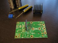
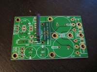
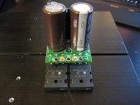
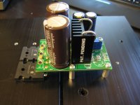
Just a quick update with a few pictures of the boards and some of the parts. I'll be building these up tomorrow!
The boards turned out really great, and I'm looking forward to testing this out tomorrow.
Cheers,
Owen
Just a quick update with a few pictures of the boards and some of the parts. I'll be building these up tomorrow!
The boards turned out really great, and I'm looking forward to testing this out tomorrow.
Cheers,
Owen
Attachments
excellent, when i saw you posted in the other thread i hot-tailed it over here. its going to make a nice compact amp. i do think i'm going to bail on the idea of the switcher; especially considering i already have all the parts for linear, it would need to present some real advantages.
@hypertune
yeah i think so, antek will do custom if we like, but at those voltages there are already designs in their catalogue that will fit pretty well. worth dropping them a line about group pricing though.
@hypertune
yeah i think so, antek will do custom if we like, but at those voltages there are already designs in their catalogue that will fit pretty well. worth dropping them a line about group pricing though.
Last edited:
i do think i'm going to bail on the idea of the switcher
I'll most likely still use SMPS for the power stage mostly to keep the chassis compact. Linear for the LME supply.
These look interesting:
http://www.shop-audiopower.com/pdfs/DPS500-52_EN1-5.pdf
I've had good results with Connex products but I wouldn't mind trying the Audiopower. The overall dimensions are good for me, and apparently particular attention has been paid to output ripple. Some interesting info here:
http://www.diyaudio.com/forums/class-d/174301-dps-500-innovative-power-supply-audio.html
ahh right, nah i have plenty of options for the linear, but i ordered some of opcs because they'll fit nicely. most likely i'll try a few different ones, i'll use lt1085/1033 in place of lt317/337 though. i might also try the gold reference super regulator as getting 55v isn't a problem at those currents, as well as salas regs
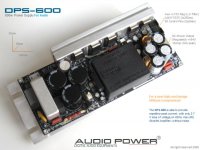
I have been in contact with Roberto (DIYAudio member) who is involved with the design of the Audiopower products. For "The Wire" amp, he suggested their DPS-600 which is intended for class A/B amps.
Roberto said it would be possible to configure it with say, 55V main and 65V aux.
As you can see in the attached pic, the aux is LC filtered and regulated with
LM317/337.
The only potential issue he raised was that high bias current may require additional heatsink.
Roberto said it would be possible to configure it with say, 55V main and 65V aux.
As you can see in the attached pic, the aux is LC filtered and regulated with
LM317/337.
The only potential issue he raised was that high bias current may require additional heatsink.
Attachments
Hello gents.
Owen brought the PCB's over to the luncheon we attended. They look great. Very good build quality on the PCB .
Owen brought the PCB's over to the luncheon we attended. They look great. Very good build quality on the PCB .
I have been in contact with Roberto (DIYAudio member) who is involved with the design of the Audiopower products. For "The Wire" amp, he suggested their DPS-600 which is intended for class A/B amps.
Roberto said it would be possible to configure it with say, 55V main and 65V aux.
As you can see in the attached pic, the aux is LC filtered and regulated with
LM317/337.
The only potential issue he raised was that high bias current may require additional heatsink.
looks good, i can't see in the pics, but as discussed the main output is the most suitable place for the main star ground, this requires some way of accommodating the return connections neatly and securely. also there are LC filters and LC filters, it would be good to see some sort of detailed noise performance characteristics at the front end and regulated main outputs and not just limited to audio bandwidth
Owen:
I was searching for LME49830 bias and I came across this post where you mention testing bias levels in 10mA increments:
http://www.diyaudio.com/forums/soli...ks-using-national-lme49830-2.html#post2163635
Would it be possible to get some more detail regarding these tests? (I mean, it's not like you've got any thing else to do right? 😀 )
qusp:
In the PDF I linked to earlier http://www.shop-audiopower.com/pdfs/DPS500-52_EN1-5.pdf there is a graph showing HF noise up to 500khz on the main DC output.
As you know, my preferred units of measurement are HP/RPM so I'd appreciate it if you'd give me your opinion. 😀
Last edited:
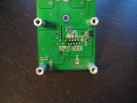
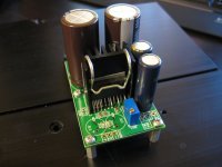
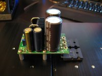
I figured I'd post up a few pictures of the completed amp here so people can see how it looks. I should hopefully get around to testing it either tomorrow or the next day. I'm waiting on an order for a few parts to build up the regulated front end, then I should be able to test everything.
Overall it's a pretty easy build, with the exception of the heatsink for the LME which is a bit of a pain to install. The second time I did it it was much easier, so I'll post up some instructions to hopefully help people out.
The amp in the pictures is built up for DC coupled differential inputs, and a star grounding setup back at the PSU. I'll detail all the construction options in a build thread once everything is nailed down.
Things still to do are:
1. Establish an optimal value for the gate resistors
2. Establish optimal values for the CComp filter at a few power levels.
3. Establish the "Sweet Spot" for bias.
I'll be doing all this via measurements and confirming with some listening tests. I have a pretty good idea of the above already based on my prototypes, but I'll be confirming that those values are still optimal given the new boards and different PSU arrangement.
igor0203:
I did get your PM, and I've added you to the list.
HYPERTUNE:
That's a very nice looking supply! I'll have to read up on it, especially if they have noise measurements.
As for the bias, I'll post some measurements up on Wednesday with details. On my prototype boards the ideal bias location was between 350 and 400mA per channel. Beyond that, there was very little reduction in distortion, and below that, the distortion started to climb up gradually. If you go higher into class A then you do get slightly lower distortion above 10kHz or so, but I doubt it's worth the added heat. I'll post graphs and people can decide what they'd like to do given their application.
Cheers,
Owen
Attachments

its so cute!! hard to imagine that little cutie putting out >300W haha
@hypertune, indeed like opc said it really is a nice looking supply. i wish the noise graph focused in on problem areas, but its sure better than nothing and it gives a good idea of where i will need to focus my efforts. i'll still be trying adding a filter at the output with a small pcb of my own, just need to check current ratings on those murata parts, i wonder if i could splice in my own regulator in place of the lm317, i mean they are reliable performers, but i'm not a huge fan, even the lt317/337 betters them.
@hypertune, indeed like opc said it really is a nice looking supply. i wish the noise graph focused in on problem areas, but its sure better than nothing and it gives a good idea of where i will need to focus my efforts. i'll still be trying adding a filter at the output with a small pcb of my own, just need to check current ratings on those murata parts, i wonder if i could splice in my own regulator in place of the lm317, i mean they are reliable performers, but i'm not a huge fan, even the lt317/337 betters them.
Last edited:
Owen, thank you! Those boards look sexy as hell! 🙂
I'm going to order case for it...could you tell me which would be more suitable? I'm aiming for 70/60V supply or in other terms, for 225WRMS 8ohm/450WRMS 4ohm?
Pesante Dissipante 3U
or
Pesante Dissipante 4U
Regards,
Igor
I'm going to order case for it...could you tell me which would be more suitable? I'm aiming for 70/60V supply or in other terms, for 225WRMS 8ohm/450WRMS 4ohm?
Pesante Dissipante 3U
or
Pesante Dissipante 4U
Regards,
Igor
Indeed. Even harder to prove a single pair can achieve that target.hard to imagine that little cutie putting out >300W
Opc,
nice layout.
Can you give a source/s for the chip clamp?
well at least the spec on the fets would have us believe its possible. i guess we'll see. i don't need anywhere near that.
they are the double device packages from memory so who knows......
they are the double device packages from memory so who knows......
Last edited:
Owen,
If the GB is still open, please put me down for
2 - PCB's without part kits.
4 - Full kits which include the PCB.
2 - extra lateral mosfet pairs
Thanks!
If the GB is still open, please put me down for
2 - PCB's without part kits.
4 - Full kits which include the PCB.
2 - extra lateral mosfet pairs
Thanks!
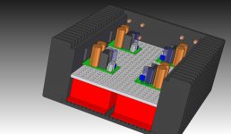
I'm toying with the idea of a 4 channel amp with dual Audiopower SMPS.
The SMPS heatsinks would be attached to the chassis heatsinks as recommended by Roberto to deal with the quiescent current.
Any comments? Any issues with positioning the Mosfet's as shown? (please excuse the very simplified model)
I like the idea of having a shield between the SMPS and amps. My intention is to have a multi-pin plug supplying all 4 balanced signals from my source (MiniDSP) along with power toggle and possibly mute.
Attachments
- Home
- Amplifiers
- Solid State
- "The Wire AMP" Class A/AB Power Amplifier based on the LME49830 with Lateral Mosfets