Your order says 1 filter kit to match a 4 ohm Pro, and 2 filter kits to match an 8 ohm Pro.
4 ohm filter kit should have '153' inductors, and '684' and '474' capacitors.
8 ohm filter kits should have '103' inductors, and '155' and '684' capacitors.
Let me know what's missing and I'll straighten it out 🙂
The resistors are for gain setting on the Pro's. There's a table on the back of the Pro PCB describing what resistor values to use for each gain setting. Default gain is 20dB, there's resistors for 23/26/29/32/36dB gain if I remember correctly.
I have a technical question regarding the Wiener Pro, would the Pro ok if
1. the input voltage is 47V?
2. the input voltage polarization is inverted?
Thanks
1. the input voltage is 47V?
2. the input voltage polarization is inverted?
Thanks
The card doesn't have reverse voltage protection designed into it, you'll damage the card if you feed it a negative power supply voltage, so don't do that 🙂
I recommend "18-36V" as the power supply voltage range for the board. But it might be possible to go higher.
According to their datasheets, the absolute max voltage on the TPA3250 chip is 50V and the absolute max on the LM25018 DC/DC converter is 52V, and the capacitors on the input power supply rail are 50V rated. However TI recommends 38V as the maximum recommended operating voltage for the 3250, and they've probably made those recommendations for a reason.
I'd also have to double check a couple things on the design, namely:
- The DC/DC converter has a tendency to have its output voltage creep up at increasing power supply voltage, it varies somewhat over the 18-36V range but stays within limits. If the output of the converter goes above 13V, this would exceed the absolute maximum voltage for the GVDD and VDD supplies on the TPA3250 chip and possibly damage it, I'd have to check this.
- I don't recall if the resistor divider I'm using for power supply voltage sensing will clip the ADC of the microcontroller at voltages that high.
So for now, not recommended until I check those things. And if you do, I make no guarantees that the card will function correctly.
The card doesn't have reverse voltage protection designed into it, you'll damage the card if you feed it a negative power supply voltage, so don't do that 🙂
I recommend "18-36V" as the power supply voltage range for the board. But it might be possible to go higher.
According to their datasheets, the absolute max voltage on the TPA3250 chip is 50V and the absolute max on the LM25018 DC/DC converter is 52V, and the capacitors on the input power supply rail are 50V rated. However TI recommends 38V as the maximum recommended operating voltage for the 3250, and they've probably made those recommendations for a reason.
I'd also have to double check a couple things on the design, namely:
- The DC/DC converter has a tendency to have its output voltage creep up at increasing power supply voltage, it varies somewhat over the 18-36V range but stays within limits. If the output of the converter goes above 13V, this would exceed the absolute maximum voltage for the GVDD and VDD supplies on the TPA3250 chip and possibly damage it, I'd have to check this.
- I don't recall if the resistor divider I'm using for power supply voltage sensing will clip the ADC of the microcontroller at voltages that high.
So for now, not recommended until I check those things. And if you do, I make no guarantees that the card will function correctly.
Noted with thanks.
Also, I'd like to confirm that, if I connect transformer to "transformer inputs", do I need to remove the capacitors C41 - C44? (mentioned in post #121)?
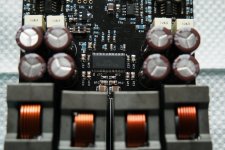
The capacitors you have to remove are labelled incorrectly on the board silkscreen, but it's the four 1uF, yellow film capacitors. Transformers then attach to the TPA facing side of the capacitor footprint. I'll have a look at a board when I get home.
Anyway I've got a few people asking me about boards...
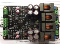
As it stands right now, I've got one fully assembled Pro prototype, configured for 8 ohms. I've got the parts to build two more 8 ohm Pro's and two more 8 ohm PBTL cards.
15uH inductors used on the 8 ohm stereo Wiener cards are out of stock until April or May, and there isn't really an alternative part that's available - Sagami 7G14 fits in the same spot but adds about 10 bucks to the cost of the card, and has to be ordered from the opposite end of the world. I haven't found any other suitable inductors that have the flat L-vs-I characteristic that I want, and fit in the same footprint.
I could use 10uH + 330nF for 8 ohm cards, which has a higher cutoff frequency, but is suitable.
I've got to get a couple other projects off my plate first, once that's done I'll get another group buy started.
The capacitors you have to remove are labelled incorrectly on the board silkscreen, but it's the four 1uF, yellow film capacitors. Transformers then attach to the TPA facing side of the capacitor footprint. I'll have a look at a board when I get home.
So it means to remove the four caps, then connect the transformer outputs to the pins of capacitors that connects to 3250? (red squared pins)
Attachments
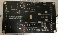
Correct.So it means to remove the four caps, then connect the transformer outputs to the pins of capacitors that connects to 3250? (red squared pins)
The alternative, and originally intended method would be to remove R13 through R16 on the card (not R14 through R17 as the silkscreen says, whoops)... leave the caps in place, and use the specified transformer inputs. But doing that's harder, I'd say do the cap method exactly as you've shown.
It's a version 0.99 prototype, a few design mistakes were made, at least I got the audio and power stuff right 🙂
Thanks.Correct.
The alternative, and originally intended method would be to remove R13 through R16 on the card (not R14 through R17 as the silkscreen says, whoops)... leave the caps in place, and use the specified transformer inputs. But doing that's harder, I'd say do the cap method exactly as you've shown.
It's a version 0.99 prototype, a few design mistakes were made, at least I got the audio and power stuff right 🙂
Besides this flaw, is there other flaw that you could remind those v0.99 prototype users?
Hi gmarsh,
A parcel arrived for me today containing
my Wiener amp, Thanks so much for
building this little amplifier for me, i'm
very much looking forward to the weekend
when i'll have my first listen! Thanks again,
very much appreciate your time and effort.
Dave
A parcel arrived for me today containing
my Wiener amp, Thanks so much for
building this little amplifier for me, i'm
very much looking forward to the weekend
when i'll have my first listen! Thanks again,
very much appreciate your time and effort.
Dave
Ditto that. Are there any PCBs or kits left?Are there any kits left?
Hi GMarsh.
I'll happily buy one of those 8ohm Pros. Let me know if I'm the lucky guy and I'll PayPal you.
Rgds
I'll happily buy one of those 8ohm Pros. Let me know if I'm the lucky guy and I'll PayPal you.
Rgds
- In-circuit programming of the microcontroller doesn't work, but that's not really an issue for end users. Got around it by building a programming jig for loose chips.Thanks.
Besides this flaw, is there other flaw that you could remind those v0.99 prototype users?
- The TPA3250 footprint sucks for hand placing/soldering/rework. Also not really an issue for end users.
- I'm not a fan of the plug-in resistors for gain switching, in hindsight I should have used DIP switches. It's hardly elegant, and people are probably gonna lose the resistors 🙂
- In-circuit programming of the microcontroller doesn't work, but that's not really an issue for end users. Got around it by building a programming jig for loose chips.
- The TPA3250 footprint sucks for hand placing/soldering/rework. Also not really an issue for end users.
- I'm not a fan of the plug-in resistors for gain switching, in hindsight I should have used DIP switches. It's hardly elegant, and people are probably gonna lose the resistors 🙂
Thanks! That's already an excellent built.
Can you briefly describe the possible reasons for different color/status of LED?
For example, solid green means everything ok. How about the possible cause of solid red? Is there other status like blink green / red?
LED off: amp is off (disabled, or unpowered)
Green LED: amp is running, all is good
Amber LED: amp is either clipping (blinking amber from time to time) or overtemperature warning is active (solid amber). Both warnings come out of the same /CLIP_OTW pin of the TPA3250.
Red LED: amp fault has occurred. Either overcurrent protection kicked in (in which case the amp will flash green/red and you'll probably hear pops coming out of your speakers) or the amp has reached the overtemperature shutdown threshold.
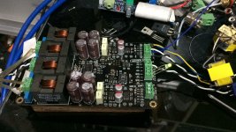
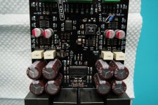
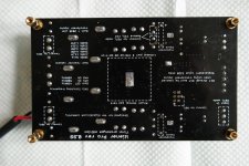
In ref to a softer Right channel (as label) for the Wiener Pro.
The one that had problem looks different from the underside, there is solder on all of the exposed copper for the heatsink.
I also attached close up of the IC and underside of the problem board.
The one that had problem looks different from the underside, there is solder on all of the exposed copper for the heatsink.
I also attached close up of the IC and underside of the problem board.
Attachments
- Home
- Group Buys
- "The Wiener" TPA3118 amplifier, group buy #3 + "Wiener Pro" prototypes.