Do I connect the 50 ohm resistor to the board output permanently, or just for the measure?
Just for measurement, the TWTMC-STS has the 50 ohm resistor on board.
Thanks. I measured with 50 ohm and its a perfect sine now.🙂
I power with 15 Vdc.
Is it worth to power the STS board with separate low noise supply or is it enough what it gets from the Ian's Fifo board?
I power with 15 Vdc.
Is it worth to power the STS board with separate low noise supply or is it enough what it gets from the Ian's Fifo board?
We have measured the best phase noise of the STS board with 5VDC power supply.
Since Ian's FIFO should be 5V tolerant the best way would be separate clean 5V regulator.
Although powering the STS directly from Ian's board it's even fine and it's simpler.
Since Ian's FIFO should be 5V tolerant the best way would be separate clean 5V regulator.
Although powering the STS directly from Ian's board it's even fine and it's simpler.
Hi,
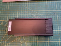
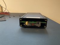
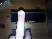
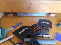
I have put some damping material in the clock units that I had left from some loudspeaker design.
Below the pcb is the black foam, on the component side I use some filter/isolation fabric as per Andrea’s proopsal.
The black foam dampens the resonance of the box very nicely. I put it on the side of the lid to keep it from resonating.
Regards,
Attachments

cables, ground loops and grounding
If you took Andrea's suggestion and used battery power, you are way smarter than me and can ignore this.
As long as I can remember I've had a small ground loop sound in one channel. That classic sizzle hash noise mostly from the tweeter. From 2-3 feet inaudible. I chased it from time to time. Kind of irritated me but nothing so bad it warranted much work.
I used a self made linear power supply for my first WTMC and for the new one. You may recall that I took some heat for soldering a pigtail to TWTMC and later found some properly terminated cables to replace the pigtail. In the process of swapping around RF cables of various quality while I wait for my RG400 to arrive from China, the ground loop disappeared. Gone. Nada. Dead silent goodness. Then when I put in properly terminated cables it was back.
So the hamsters on the wheel in my head went nuts. Not only does the RF cable influence sound, it can impact ground loops.
I have finally eliminated the ground loop, and got great sound by grounding the coax shield at the WTMC PCB. Grounding the termination at the FIFO end helped the ground loop, but absolutely collapsed the sound stage and messed with sound quality. Taking away the ground path at the FIFO (it is still 0 ohms to ground, but not a separate ground path) and giving a good ground path from the RF shield at the WTMC eliminated the ground loop and returned the big open airy sound stage and great sound.
It will be interesting to see how all this is affected by the RG400 SMA terminated cables.
I was apprehensive about grounding as the WTMC signal ground is not shared with the PS ground. Both the DAC and the WTMC have 3rd wire safety grounds that plug into the same power bar. But I have found it can be tricky to avoid ground loops. If you are using an AC power supply and have a ground loop perhaps this will give you some places to look.
Hello,
I decided to go for one piece extruded aluminium rectangular tubes. They are leftovers i took home from work instead of having them melted.Whenever there are several parts connected together chances something will " rattle " are bigger.
My clock circuits are still in Italy waiting for clocks to arrive. In the pdf the board is wrapped in a fabric or foam to keep it from wandering around.
The clock is attached with 2 leads to the circuit. The clock is the main element that has to be isolated from vibration so have it connection by two TINY wires is probably the best way to go. The board will pick up a bigger amount of vibration because of its dimensions.
Isn't a clock sensitive to vibrations because the elements inside do not consist of one " lump" like you well get by vacuum impregnation? IF so wrapping it in foam ( wanna try a cork) can isolate it from airborn vibration and also dampen the clock's little metal cover.
Attaching the foam to the circuit will probably introduce more vibration to the clock. I would rely upon the thin wires.
With just these two hairlike wires the only vibration to worry about should be the airborn or not? So should we place the 6 aluminium tubes in a sort of soundproof box.
I have done some projects with double sided sand filled wooden boxes and recently added some heavy diy lead objects to my speakers. But soundproof is a different matter. Do these clocks have a frequency range that they want keep knocking? Then we could adjust the material to be used.
Any ideas are welcome. Normally i would check results with a stethoscope but for a tiny clock we need something else. Can measure isolation with my little Dayton microphone and AudioTool software.
Greetings,Eduard
Attachments


Hello Canada and the rest of the crew.
If i remember well the rg400 is double shielded or not?
Suppose you would have 5 single shielded cables and you need to make a connection between two boards. The 5 cables are terminated at the factory. Unless Andrea or Ian tells us otherwise we should use them according to the book. If there is a hum they all should hum.
Maybe in another set the hum wont be as bad. But if a not 100% connection causes a hum loop there should be a hum loop in Italy but one in Canada too.
So if we have a total of 9 SMA terminated cables they should be identical worldwide. Would be nice if all the people using these 9 cables will know that if a few have a hum attack it wont be solved by messing around with these nine cables.
Greetings,Eduard
IF i remember well the i2s between fifopi and DDDAC board is only grounded on fifopi side.
Is there a preferred orientation for the xtall? After mounting it to the board is it best to stack the board in its case like a book or keep the xtall flat? I’m guessing the more on edge orientation might be preferable.
My understanding RG400 has a couple of key specs.. It is double shielded and it uses silver plated copper conductors and is rated for 14gHz. It is a particularly low loss RF cable. Andrea's suggested max of 1m has a loss of 0.3db. And it will be the same where ever it is bought or used.Hello Canada and the rest of the crew.
If i remember well the rg400 is double shielded or not?
Suppose you would have 5 single shielded cables and you need to make a connection between two boards. The 5 cables are terminated at the factory. Unless Andrea or Ian tells us otherwise we should use them according to the book. If there is a hum they all should hum.
Maybe in another set the hum wont be as bad. But if a not 100% connection causes a hum loop there should be a hum loop in Italy but one in Canada too.
So if we have a total of 9 SMA terminated cables they should be identical worldwide. Would be nice if all the people using these 9 cables will know that if a few have a hum attack it wont be solved by messing around with these nine cables.
Greetings,Eduard
IF i remember well the i2s between fifopi and DDDAC board is only grounded on fifopi side.
I am not an electronics engineer and like most hobbyists find ground loops challenging. In my experience there is no one size fits all to solving a ground loop. I have had cases where changing the gauge of the conductor can change whether you see ground loop or not. In my case, I think it is amazing that I do not have hum. There are 25 separate power supplies in a system that has all triode gain stages and hi efficiency speakers. But it has been a labor of love to pay attention to star grounds, twisted wires and layout to keep the noise down. On a good day I can put ear tight to the tweeter and not tell if the system is powered up. I am happy with that.
I did not really think about the clock as a factor in ground loops, but it is certainly a prime candidate. Battery power and disconnecting from mains eliminates that issue.
In my case I'll sort it out, but it makes no sense to worry about it until my RG400 SMA terminated cable arrives. Right now I have a ufl termination at the FIFO end and a cable spec'd for 2.4gHz vs the RG400's 14 gHz. Who knows if the RG400 makes it better or worse until I plug it in and have the clock sitting in its final place. Then it will be playing around with grounding the power supply vs the RF cable vs letting it float relative to the rest of the system.
Loops are loops whether from power supplies or not. For example, stereo RCA signal cables not tight together form a ground loop.
Good point. Fair to say if you DIY by buying leggo pieces like commercial cables, PCBs and power supplies, you have less risk of finding out about ground loops. If you scratch build everything, a little more attention required, and its not always obvious where it tips over into audible noise territory.
Hello,
You could even carve it in stone.
A ground loop, is a ground loop and should always be avoided. Even if it doesnt create audible noise better always consider it as something that will degrade sound one way or another.
Surely if you end up with a mix of boards from Andrea, Doede and Ian pretty likely you have to take extra care once you combine things in a way that hasnt been done before.
Greetings, Eduard
P.s Of course the famous 3 dont know all the ins and outs of each other circuits.
Can someone share the mouser part number for the SMA connector used on the sine wave to square pcbs use for the FiFoPi ?
Thanks
Thanks
Can someone share the mouser part number for the SMA connector used on the sine wave to square pcbs use for the FiFoPi ?
Thanks
I got them at superbat together with assembled sma cables. They have them much cheaper than mouser.
Custom Cable Assemblies | No Minimum Order
Thanks guys and will use superbat as need to order the cables anyway. I did have a look there the other day and so many options, need to ensure I order the right one
Hello,
I am right i came across the thicker coaxial cable used by Andrea to connect his game of clocks set up. Also saw one that is much thinner.
IF i am right you need to use both cable and printboard part of the connection to maintain the right impedance?
I would try to get the same brand for both parts so they will give a perfect connection.
I know the Fifopi ( or know the reclockpi) is connected to the DDDAC mainboard where on the Canadian side both UFL board and cable part are used and on the other side there is just a solder connection.
I read several times that the connection between Fifopi and mainboard should be equal length and as short as possible.
Then it would logical that the properties of the complete connection should be according to the book.
Maybe even the smallest distance possible between the reclockpi and the mainboard.
Greetings, Eduard
About the coaxial cables to connect oscillators and DBM I suggest again to source them as finished items from Superbat.
Hello,
As pictured in the PDF maybe reduce straight angled plugs on one or both side to reduce cable length to an absolute minimum.
Because my chassis are a little deeper, i think than needed would slider the print deeper inside offer a theoretical tiny bit of extra screening..
Should the SMA chassis part be mounted on the front plate, isolated or not?
Greetings, Eduard
- Home
- Group Buys
- The Well Tempered Master Clock - Group buy