Uh, no it doesn't. Where was that decreed. The Bible? Please cite your reference.No. Extraordinary claims require extraordinary proof. ....
Not a claim. Simply an observation that may be of useful to some and offend others. Gotta go now. I need not waste time on this subject when I can be listening to a great system even if it's a figment of my imagination in your imagination.
I have some trouble correlating this:
"The best SQ phono is from direct-to-disk-lathe recordings. No tape, no digital."
with the pursuit of low close in phase noise. I have more experience with the rotational stability of disks than most having developed systems for writing clock tracks on magnetic disks (its really hard to get 1,000,000 equally spaced magnetic domains on a spinning platter +/- 0.25) so this drive to get even -140 dB timing accuracy when something with at best .1% (-80 dB) wow is considered superb. Maybe there is some conversion from phase to amplitude that is significant. If so then it should be possible to measure it and fix it.
I would not be surprised if the other surrounding efforts necessary to deploy one of Andrea's clocks has more contribution than the clocks own performance to the overall sound quality.
While I have the Timepod and two carefully selected Wenzel oscillators for it ready I have been way too busy to assemble the pieces.
Uh, no it doesn't. Where was that decreed. The Bible? Please cite your reference.
I can help with this.
Extraordinary Claims Require Extraordinary Evidence: The Case of Non-Local Perception, a Classical and Bayesian Review of Evidences
"Do you have an extra brain to check that?"
Yes, a few of them. They are my listening panel participants.
Evidence of Experimental Bias in the Life Sciences: Why We Need Blind Data Recording
It’s just hard to take these claims of yours seriously
Last edited:
I have some trouble correlating this:
"The best SQ phono is from direct-to-disk-lathe recordings. No tape, no digital."
with the pursuit of low close in phase noise.
You are not alone, but I have for a long time concluded that attempting to apply any formal logic principles to subjective audio evaluation is a lost cause.
I have presumed nothing.
you are not the only person in the thread btw
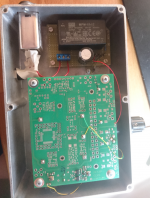
Hi Doede,
Nice work!
The previous driscoll with sc-cut crystal of Andrea is in a (sort of) dil14 package..... it fits on top of the fifopi but needs separate power supply.
If you like to do more comparisons I can lent you one of these and also a crystek (both 45mhz) Please let me know if you are interested.
You need 3v (or 3,3v) and 6v (or 6,6v) power supplies.
Groeten,
I wonder howmuch the AT Cut and first gen SC Cut Andrea's design would perform in the test ? Maybe a 9 ?! Many experienced an improvement over the Crysteck 957 or the NDK-SA.
I also assume these DIL stack with vias are always a trade off over direct pcb soldering when high frequencies are involved ! Are they with 22/24 M hz crystals speed ?
Nice review anyway.
Really? A paper from frontiers in Psychology to support the claim that I prefer the sound of my system in my home using Andrea's clock? What is extraordinary about that?
BTW, it appears the paper you cite aims to prove we have extrasensory perception or "Non-Local Perception" as they refer to it. Are you sure that's where you wanted to go? To be clear, I just turn on the system and use my ears and report what I hear. And I fully appreciate that we all perceive the same event differently. Kind of ordinary, actually.
I'm afraid you don't meet the pre-requisites to have any educated discussion on this topic. If you go as far as matching what is written black on white to your pre-conceptions, then there's nothing else to add.
Good luck fooling yourself, humans are masters to that.
Good luck fooling yourself, humans are masters to that.
@ syn08:
> As you can clearly see, as long as you don't have a catchy story to add to your results, nobody gives a **** on your results in this thread.
I did not expect constructive ideas from the hi end kit solder brigade.
Let them do their lyrics. I'll keep away from that.
But there have been most valuable email messages which will probably
result in some work for DHL and confirmed or debunked results.
It is funny that in a field of half a dozen 5 MHz oscillators the one with the
digital €12 Mean Well power line switcher has the least birdies and the best PN.
Sorry, no Lithium and no 3 cascaded regulators.
There is nothing but a power line filter, an added electrolytic and a 10 turn pot
connected to the oscillator's Vref and Vtune to pull the frequency a few Hz.
The OCXO carrier board is only there for the mechanics and the push-pull
17 dBm amplifier.
@1audio
> Not quite- I am. In particular on the 10 MHz it seems one oscillator was right at
> the noise floor. What determines the noise floor?
> The reference oscillator or the noise of the ADC's?
Absolutely double sided thermal noise, -177 dBm rt Hz or so. With enough signal
power more is possible in principle, but there are error sources on would not expect.
For example, the power splitters that distribute the signal and the reference to 2 ADCs each.
This is a simple SMD part in the timepod, but inside, there is a 200 Ohms resistor
that connects the 2 outputs, just like in every Wilkinson divider.
The thermal voltage of this resistor adds to the 2 inputs in antiphase. That is
an error when you assume cross correlation of truly independent signals.
You may see results that are too good to be true.
J.Miles writes that when used with 2 references, the quality of the ADCs
plays a much smaller role since their errors average away with the
cross correlation.
< http://time.kinali.ch/rohde/noise/how_low_can_they_go-2013-poddar_rohde_apte.pdf >
Gerhard
Attachments
Last edited:
Uh, no it doesn't. Where was that decreed. The Bible? Please cite your reference.
Christopher Hitchens? That would be the Anti-Bible.
"What is asserted without proof can be dismissed without proof"
Last edited:

I did not do that with mine but make sure they cannot injection-lock
each other. That would make the 3-cornered hat meaningless since
they were no longer independent.
I have everything in a 3 HU 19" box: timepod, references and a
switchable delay line with 6 1-to-6 SMA coax relays that can
bring every signal between 4 and ~110 MHz in quadrature.
With the timepod, the switchable delay is very seldom needed
but there was space left and I have too much boxes on the table.
The important signals are all on front plate SMAs to be able
to change the configuration.
Last edited:
But almost unanimously we have been rewarded with substantial leaps in sound quality .
Really? A paper from frontiers in Psychology to support the claim that I prefer the sound of my system in my home using Andrea's clock? .
These are two different statements, the second of which is non-contentious. A preference does not imply a 'leap in sound quality'.
<snip>I would not be surprised if the other surrounding efforts necessary to deploy one of Andrea's clocks has more contribution than the clocks own performance to the overall sound quality.
I totally agree, but to be fair we must state, that most if not all of the other surrounding efforts would be deemed as unimportant as well.
Which illustrates one of the problems, basically a holistic approach is needed and if one favours the illusion of a certain restricted set of measurements is already telling the whole story, then something important is missing.
Otoh to rely on listening tests without proper controls might be not sufficient for any external observer but could be a better fit for reality.
The "extraordinary proof" is a nice idea, but often it is questionable what constitutes a "extraordinary claim" and further if any of the requested "proof" is even possible (considering the human nature), especially if no one is able to write down which kind of "proof" he would accept as sufficient evidence.
I am a simple man, I plug the clock in. If it sounds "better", meaning I like it more than "another", it stays in my audio and I have more pleasure. Next steps are tweaking the surroundings... I like measurements as well, but the veto is always "do I like what I hear?"
As earlier said, I am not testing for datasheets or magazines.
I like to say to everyone: take my contributions as motivation to try for yourself.. If you never listened to any of these products and give judgmental comments, it is more the fraction of arm-chair audiophiles 😀
I read many comments on DIY and I find many helpful, as they give interesting feedback and perspectives. I also note, that the number of people who build stuff and make it available to other DIY are very limited.... The comments on their work, sometimes totally out of relation. This is a DIY forum, so let's DO something and share your work. Other wise, stay in your arm chair and start enjoying music.
This is not university where academic discussions from/with/for woke people are "the meaning of life" (Nice movie by the way, for all the scene Where Brian says" you are individuals!" - you know the answer, right? or watch the movie 😛 )
my 2 cents
Hello,
I think Andrea and Ian should join and write a kind of '' tutorial '' HOW to combine their creations together in the best way.
I honestly think that spreading all ( number is getting bigger each '' upgrade'') the boards in an almost randomly way is not the right way. Usually it will be done in a non logical way because the extra board will be positioned in an area that is not occupied yet on the wooden panel.
A bit like tuning your car engine with a bigger cylinder which forces you to a add a trailer to your car because it doesnt fit where it needs to be. BUT all your friends can see you had the guts to get the thing everyone is talking about.
Very few people will question if this improvement is a real one .
Maybe there is someone who removed the original cylinder and took it to his friend who has a nice CNC milling/router machine to add only 25 % of the CC increase the big one is offering BUT because it stays where it should be it gives the same improvement without the use of a trailer.
There should be a bit more guidance. I am sure there are boards that care a lot about the length of its power supply cable while others dont mind that much.
The I2S cable MUST be short that is carved in stone.
Some cables should only cross at square angles?? Just like a hardwired tube amp there are some rules.
But here everything digital and no buzz from heaters everyone seems to do things like there are no rules. There must be or not?
Greetings, eduard
@1audio, gerhard & Andrea: Just a brief digression ... I am considering a spectrum analyzer and since the Timepod uses quality high speed ADCs: Do you know if somehow the Timepod can be used as a spectrum analyzer? Would be great ...
Cheers,
Jesper
Cheers,
Jesper
- Status
- Not open for further replies.
- Home
- Source & Line
- Digital Line Level
- The Well Tempered Master Clock - Building a low phase noise/jitter crystal oscillator